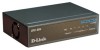
D-Link DFE-904 User Guide - Page 14
Bottom Panel
 |
UPC - 790069213014
View all D-Link DFE-904 manuals
Add to My Manuals
Save this manual to your list of manuals |
Page 14 highlights
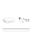
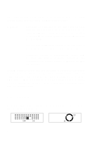
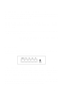
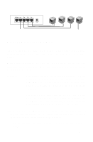
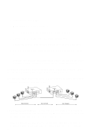
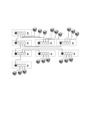
Jacks 1, 2, 3, and 4 are RJ-45 connectors for the hub's network ports. Each is wired to work with a cable from a network end node or from another hub's uplink jack. The Uplink jack is an RJ-45 jack wired for an uplink connection to another hub. This jack is part of the same circuit as jack 4; never use both of these jacks at the same time. Technical Note: The difference between the Uplink jack and jack 4 is that the transmit and receive lines are crossed in jack 4 and uncrossed in the Uplink jack. If the hub had no Uplink jack, you would need a special cross-wired cable to make an uplink connection. Use the Uplink jack only for a connection to another hub, never for a connection to an end node. Note that such a connection will require a cross-wired jack (the kind that is wired for an end node) on the other hub. Use only standard (straight-through) UTP or STP cables with the DFE-904. Category 3, 4, and 5 cables are all acceptable for 10 Mbps; only Category 5 and equivalent cables are acceptable for 100 Mbps. Network cables can be attached and detached at any time, whether the hub is on or off. Read the relevant connection instructions in this guide carefully before making connections. Bottom Panel On the bottom of the hub are two mounting holes and four indented square outlines. The mounting holes, together with the supplied screws and wall anchors, let you mount the hub on a vertical surface. The holes are diagonally oriented so the hub can face in any direction. We recommend mounting the hub with its cable jacks facing down or sideways to help keep dust off the contacts. 8
-
 1
1 -
2
-
3
-
4
-
5
-
6
-
7
-
8
-
 9
9 -
 10
10 -
 11
11 -
 12
12 -
 13
13 -
 14
14 -
 15
15 -
 16
16 -
 17
17 -
 18
18 -
 19
19 -
20
-
21
-
22
-
23
-
24
 |
 |