D-Link DGS-1024TG User Guide - Page 11
Identifying External Components
 |
View all D-Link DGS-1024TG manuals
Add to My Manuals
Save this manual to your list of manuals |
Page 11 highlights
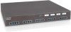
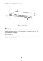
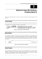
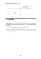
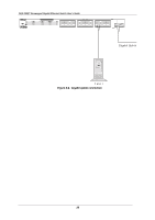
DGS-1024T Unmanaged Gigabit Ethernet Switch User's Guide 3 3 IDENTIFYING EXTERNAL COMPONENTS This chapter describes the front panel, rear panel, side panels, and LED indicators of the Switch. Front Panel The front panel of the DGS-1024T consists of an LED indicator for power and indicators for 24 individual ports for speed, full duplex, and link/activity. Figure 3-1. Front panel view of the DGS-1024T Rear Panel The rear panel contains the AC power connector and one system fan used to dissipate heat. The AC power connector is a standard three-pronged connector that supports the power cord. Plug-in the female connector of the provided power cord into this socket, and the male side of the cord into a power outlet. Supported input voltages range from 100 ~ 240 VAC at 50 ~ 60 Hz. Figure 3-2. Rear panel view of the Switch. Side Panels Each side panel contains heat vents that are used to dissipate heat. Do not block these openings, and leave at least 6 inches of space at the rear and sides of the switch for proper ventilation. Be reminded that without proper heat dissipation and air circulation, system components might overheat, which could lead to system failure. 7
-
 1
1 -
2
-
3
-
4
-
5
-
 6
6 -
 7
7 -
 8
8 -
 9
9 -
 10
10 -
 11
11 -
 12
12 -
 13
13 -
 14
14 -
 15
15 -
 16
16 -
17
-
18
-
19
-
20
-
21
-
22
-
23
-
24
-
25
-
26
-
27
 |
 |
