D-Link DSN-5410-10 Hardware Reference Guide for DSN-5000-10 - Page 34
Expansion Array Front Panel Components
 |
UPC - 790069324000
View all D-Link DSN-5410-10 manuals
Add to My Manuals
Save this manual to your list of manuals |
Page 34 highlights
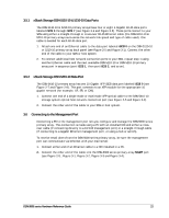
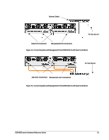
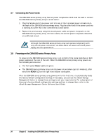
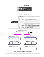
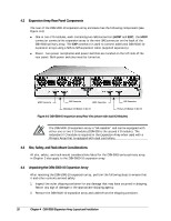
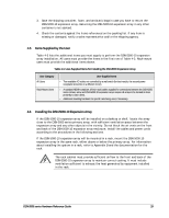
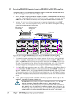
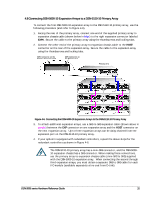
4.1 Expansion Array Front Panel Components The front of the DSN-5000-10 expansion array enclosure has the following components (see Figure 4-1): LEDs - four enclosure LEDs at the right side of the front panel provide status information about the DSN-5000 series primary array enclosure. For a description of these LEDs, see Table 4-1. Drive slots - the front panel provides access to 12 drive slots. The drive slots are arranged in four columns of 3 slots. Drive carriers - drives are mounted on a drive carrier. Drive carriers have a push-button lever for installing and removing drives, and three status LEDs (see Figure 4-2 and Table 4-2). Each carrier has a corresponding drive slot number (see Figure 4-3). Filler panels must be installed in all drive slots that are not occupied by a drive. Drive Carrier (see Figure 4-2 for Close-up View) Enclosure LEDs LED Power Fault Ready Identify Drive Slots Figure 4-1. Front View of the DSN-5000-10 Expansion Array Table 4-1. Enclosure LEDs Color Green Amber Green Blue Description ON = DSN-5000-10 expansion array is powered on. OFF = power is not being received. ON = a fault occurred with the power supply, fan, over temperature, internal module, or controllers. OFF = normal operation. ON = normal operation. OFF = normal while DSN-5000-10 expansion array is booting. After initialization, this status indicates a problem with the DSN-5000-10 expansion array. Blink = DSN-5000-10 expansion array is trying to identify the physical location of a drive using the xStack Storage Management Center. OFF = no intent of identification is being performed. 26 Chapter 4 DSN-5000 Expansion Array Layout and Installation
-
 1
1 -
2
-
3
-
4
-
5
-
6
-
7
-
8
-
9
-
10
-
11
-
12
-
13
-
14
-
15
-
16
-
17
-
18
-
19
-
20
-
21
-
22
-
23
-
24
-
25
-
26
-
27
-
28
-
 29
29 -
 30
30 -
 31
31 -
 32
32 -
 33
33 -
 34
34 -
 35
35 -
 36
36 -
 37
37 -
 38
38 -
 39
39 -
40
-
41
-
42
-
43
-
44
-
45
-
46
-
47
-
48
-
49
-
50
-
51
-
52
 |
 |