DIRECTV ASL-1 User Guide
DIRECTV ASL-1 Manual
 |
View all DIRECTV ASL-1 manuals
Add to My Manuals
Save this manual to your list of manuals |
DIRECTV ASL-1 manual content summary:
- DIRECTV ASL-1 | User Guide - Page 1
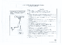
an IRD will cause the SWM ODU to be pulled out of the signal peaking mode. ASL.I 'Inc.. 110v AC Legacy Meter Examples Pacts sem.Digital SSM22. ECT likasialstoilimplath•S$S221 The I8v 0 2 4 6 8 at the "hello"screen. • (io through the IRD guided set-up. O neld Operattena Tre•litIng Kay 200$ - DIRECTV ASL-1 | User Guide - Page 2
to the IN port of the Single Port Power Pass Splitter. • Connect the SWM power inserter SWM power port to the DC OUT port of the splitter. • Connect the signal level meter [NB port to using 0 2 4 6 8 at the "hello"screen. • Go through the IRE) guided set-up. O ri,"•14 organs Titalelef Sy 30041
-
 1
1 -
 2
2
 |
 |
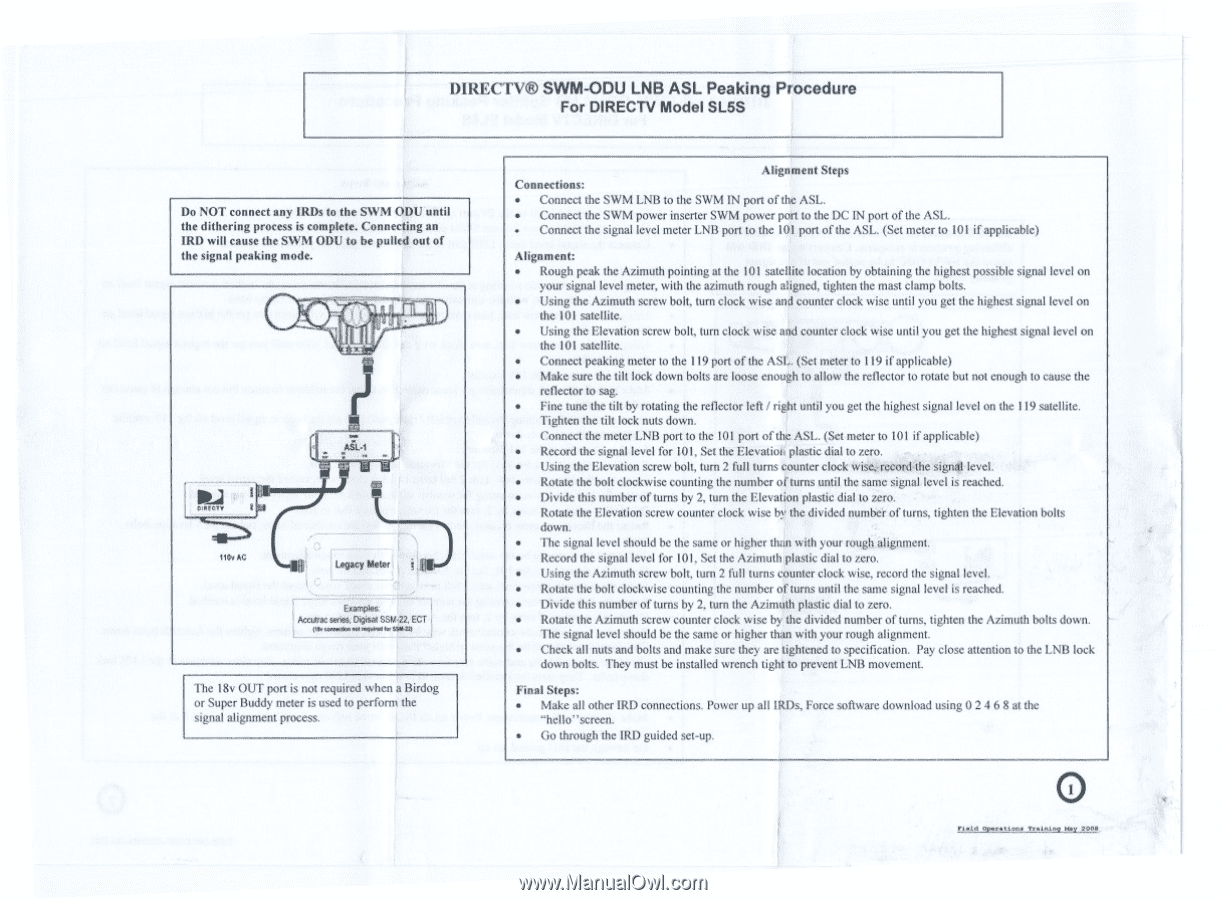
DIRECTV®
SWM-ODU
LNB
ASL
Peaking
Procedure
For
DIRECTV
Model
SL5S
Do
NOT
connect
any
IRDs
to
the
SWM
ODU
until
the
dithering
process
is
complete.
Connecting
an
IRD
will
cause
the
SWM
ODU
to
be
pulled
out
of
the
signal
peaking
mode.
'Inc..
110v
AC
ASL.I
Legacy
Meter
Examples
Pacts
se
m.
Digital
SSM22.
ECT
likasialstoilimplath•S$S221
The
I8v
OUT
port
is
not
required
when
a
Birdog
or
Super
Buddy
meter
is
used
to
perform
the
signal
alignment
process.
Alignment
Steps
Connections:
•
Connect
the
SWM
LNB
to
the
SWM
IN
port
of
the
ASL.
•
Connect
the
SWM
power
inserter
SWM
power
port
to
the
DC
IN
port
of
the
ASL.
•
Connect
the
signal
level
meter
LNB
port
to
the
101
port
of
the
ASL.
(Set
meter
to
101
if
applicable)
Alignment:
•
Rough
peak
the
Azimuth
pointing
at
the
101
satellite
location
by
obtaining
the
highest
possible
signal
level
on
your
signal
level
meter,
with
the
azimuth
rough
aligned,
tighten
the
mast
clamp
bolts.
•
Using
the
Azimuth
screw
bolt,
turn
clock
wise
and
counter
clock
wise
until
you
get
the
highest
signal
level
on
the
DM
satellite.
•
Using
the
Elevation
screw
bolt,
turn
clock
wise
and
counter
clock
wise
until
you
get
the
highest
signal
level
on
the
101
satellite.
•
Connect
peaking
meter
to
the
119
port
of
the
ASL.
(Set
meter
to
119
if
applicable)
•
Make
sure
the
tilt
lock
down
bolts
arc
loose
enough
to
allow
the
reflector
to
rotate
but
not
enough
to
cause
the
reflector
to
sag.
•
Fine
tune
the
tilt
by
rotating
the
reflector
left
/
right
until
you
get
the
highest
signal
level
on
the
119
satellite.
Tighten
the
tilt
lock
nuts
down.
•
Connect
the
meter
LNB
port
to
the
101
port
of
the
ASI..
(Set
meter
to
101
if
applicable)
•
Record
the
signal
level
for
101,
Set
the
Elevation
plastic
dial
to
zero.
•
Using
the
Elevation
screw
bolt,
turn
2
full
turns
counter
clock
wise.
record
the
signal
level.
•
Rotate
the
bolt
clockwise
counting
the
number
of
turns
until
the
same
signal
level
is
reached.
•
Divide
this
number
of
turns
by
2,
turn
the
Elevation
plastic
dial
to
zero.
•
Rotate
the
Elevation
screw
counter
clock
wise
by
the
divided
number
of
turns,
tighten
the
Elevation
bolts
down.
•
Ilic
signal
level
should
be
the
same
or
higher
than
with
your
rough
alignment.
•
Record
the
signal
level
for
101.
Set
the
Azimuth
plastic
dial
to
zero.
•
Using
the
Azimuth
screw
bolt,
turn
2
full
turns
counter
clock
wise,
record
the
signal
level.
•
Rotate
the
bolt
clockwise
counting
the
number
of
turns
until
the
same
signal
level
is
reached.
•
Divide
this
number
of
turns
by
2.
turn
the
Azimuth
plastic
dial
to
zero.
•
Rotate
the
Azimuth
screw
counter
clock
wise
by
the
divided
number
of
turns,
tighten
the
Azimuth
bolts
down.
The
signal
level
should
be
the
same
or
higher
than
with
your
rough
alignment.
•
Check
all
nuts
and
bolts
and
make
sure
they
arc
tightened
to
specification.
Pay
close
attention
to
the
LNB
lock
down
bolts.
They
must
be
installed
wrench
tight
to
prevent
LbIll
movement.
Final
Steps:
•
Make
all
other
1RD
connections.
Power
up
all
IRDs,
Force
software
download
using
0
2
4
6
8
at
the
"hello"screen.
•
(io
through
the
IRD
guided
set-up.
O
neld
Operattena
Tre•litIng
Kay
200$