Dell 1526 Service Manual - Page 13
Processor Module
 |
UPC - 883585945481
View all Dell 1526 manuals
Add to My Manuals
Save this manual to your list of manuals |
Page 13 highlights
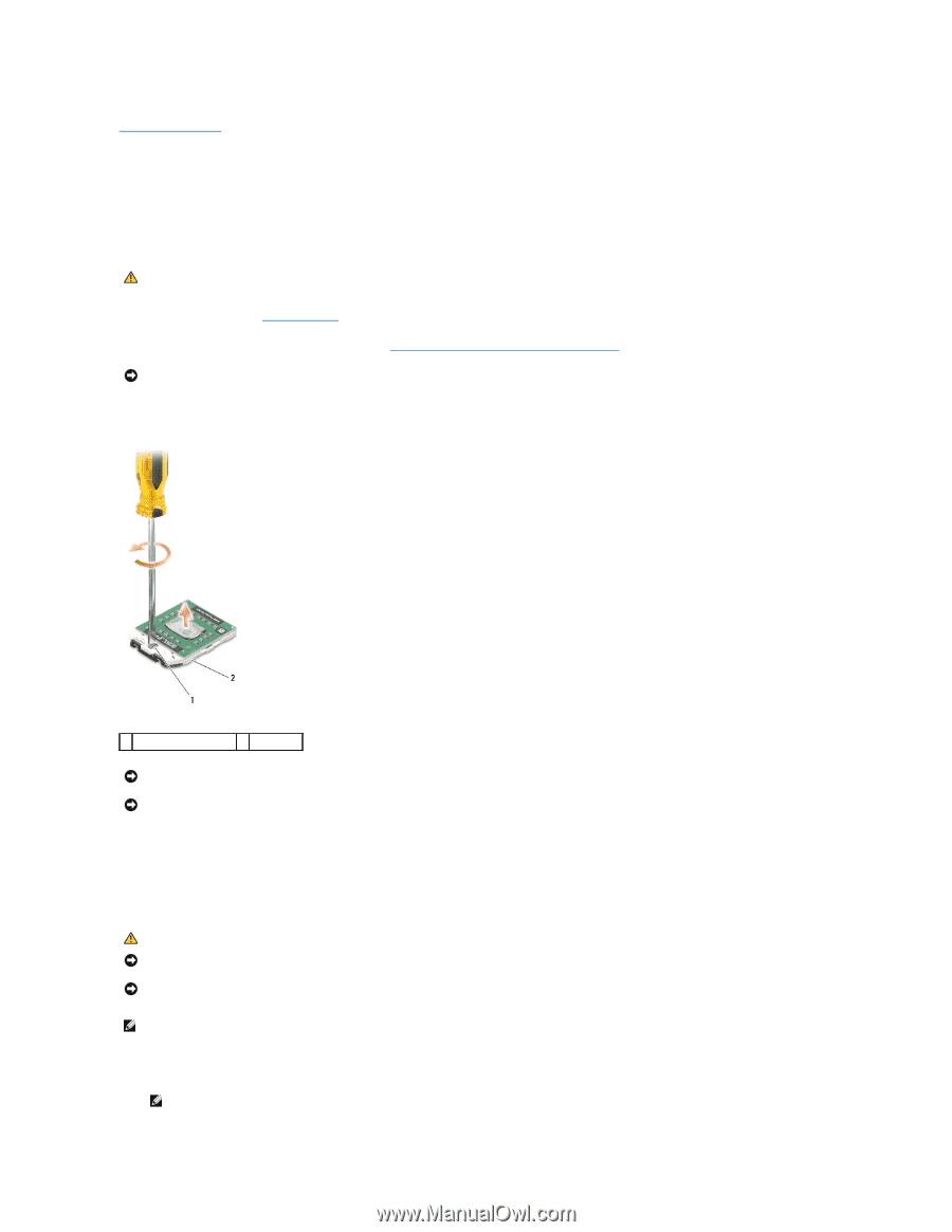
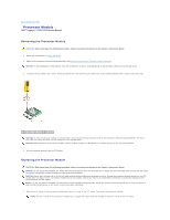
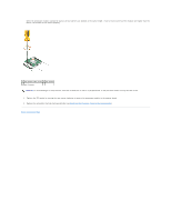
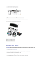
Back to Contents Page Processor Module Dell™ Inspiron™ 1525/1526 Service Manual Removing the Processor Module CAUTION: Before you begin the following procedure, follow the safety instructions in the Product Information Guide. 1. Follow the instructions in Before You Begin. 2. Remove the processor thermal-cooling assembly (see Removing the Processor Thermal-Cooling Assembly). NOTICE: To avoid damage to the processor, hold the screwdriver so that it is perpendicular to the processor when turning the cam screw. 3. To loosen the ZIF socket, use a small, flat-blade screwdriver and rotate the ZIF-socket cam screw counterclockwise until it comes to the cam stop. 1 ZIF-socket cam screw 2 ZIF socket NOTICE: To ensure maximum cooling for the processor, do not touch the heat transfer areas on the processor thermal-cooling assembly. The oils in your skin can reduce the heat transfer capability of the thermal pads. NOTICE: When removing the processor module, pull the module straight up. Be careful not to bend the pins on the processor module. 4. Lift the processor module from the ZIF socket. Replacing the Processor Module CAUTION: Before you begin the following procedure, follow the safety instructions in the Product Information Guide. NOTICE: Do not touch the processor die. Press and hold the processor down on the substrate on which the die is mounted while turning the cam screw to prevent intermittent contact between the cam screw and processor. NOTICE: Ensure that the cam lock is in the fully open position before seating the processor module. Seating the processor module properly in the ZIF socket does not require force. A processor module that is not properly seated can result in an intermittent connection or permanent damage to the microprocessor and ZIF socket. NOTE: If a new processor is installed, you will receive a new thermal-cooling assembly, which will include an affixed thermal pad, or you will receive a new thermal pad along with a tech sheet to illustrate proper installation. 1. Align the pin-1 corner of the processor module with the pin-1 corner of the ZIF socket, then insert the processor module. NOTE: The pin-1 corner of the processor module has a triangle that aligns with the triangle on the pin-1 corner of the ZIF socket.
-
 1
1 -
2
-
3
-
4
-
5
-
6
-
7
-
 8
8 -
 9
9 -
 10
10 -
 11
11 -
 12
12 -
 13
13 -
 14
14 -
 15
15 -
 16
16 -
 17
17 -
 18
18 -
19
-
20
-
21
-
22
-
23
-
24
-
25
-
26
-
27
-
28
-
29
-
30
-
31
-
32
-
33
-
34
-
35
-
36
-
37
-
38
-
39
-
40
-
41
-
42
-
43
-
44
-
45
-
46
-
47
-
48
-
49
-
50
-
51
 |
 |