Dell 1800FP Service Manual
Dell 1800FP - UltraSharp - 18.1" LCD Monitor Manual
 |
View all Dell 1800FP manuals
Add to My Manuals
Save this manual to your list of manuals |
Dell 1800FP manual content summary:
- Dell 1800FP | Service Manual - Page 1
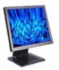
COLOR MONITOR SERVICE MANUAL CHASSIS NO. : CL-29 FACTORY MODEL: LD803H MODEL: 1800FP CAUTION BEFORE SERVICING THE UNIT, READ THE SAFETY PRECAUTIONS IN THIS MANUAL. - Dell 1800FP | Service Manual - Page 2
TROUBLESHOOTING GUIDE 11 PRINTED CIRCUIT BOARD 15 EXPLODED VIEW 19 REPLACEMENT PARTS LIST 21 PIN CONFIGURATION 26 SCHEMATIC DIAGRAM 28 SPECIFICATIONS 1. LCD CHARACTERISTICS Type : TFT SXGA LCD Size : 18.1inch Pixel Pitch : 0.2805(H) x 0.2805(V) Color Depth : 8-bit, 16,777,216 colors - Dell 1800FP | Service Manual - Page 3
There are some special components used in LCD monitor that are important for safety. These parts are marked on the schematic diagram and the replacement parts list. It is essential that these critical parts should be replaced with the manufacturer's specified parts to prevent electric shock, fire or - Dell 1800FP | Service Manual - Page 4
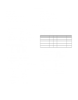
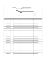
14 15 16 H/V Sync Dot Sort Polarity Clock Frequency Total Period Video Active Time (E) (A) H+ 31.469 800 640 25.175 V- 1280 1024 Front Porch (C) 16 37 18 12 16 10 16 1 56 1 40 1 16 1 32 1 32 1 24 3 16 1 48 1 64 1 18 2 48 1 16 1 Sync Duration 38 248 38 Resolution 640x350 70Hz 720x400 - Dell 1800FP | Service Manual - Page 5
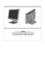
Front Control Panel 65 4 3 2 1 1. Power Button and LED Indicator Turn the display on/off and indicate the status of power management. 2. Select/Auto Button Use this button to enter a selection in the On Screen Display. Automatically adjust vertical position, horizontal position, pixel clock - Dell 1800FP | Service Manual - Page 6
WIRING DIAGRAM Connector Ass'y P/N: 6631T25008Q MAIN PCB Connector Ass'y P/N: 6631T20015R MATAL FRAME J705 J801 J702 P902 J710 CN3 CN2 CN1 CN7 CN6 CN4 CN5 CN_C02 CN_C01 CN301 Connector Ass'y P/N: 6631T20008U MODULE(Need to change LM181E06) Connector Ass'y P/N: 6631T11012P -6- - Dell 1800FP | Service Manual - Page 7
BLOCK DIAGRAM Power Board -7- Inverter CTL Power CTL Module CTL 12V LCD Module Inverter Micom 68HC08-BD48 H/V Sync 12V R,G,B differential LVDS (LVD S823) Out - CLK DE ,H/V Sync out R,G,B /Odd Memory (KM416S102BT) 3.3 VM M-CLK Address Data 48 Bit 5V 5V - Dell 1800FP | Service Manual - Page 8
signal from the Scaler to the receiver of module. 3. Power Part. This part consists of the one 5V, two 3.3V and one 2.5 regulators to convert power which is provided 12V, 5V in Power Board. 12V is provided for inverter, 5V is provided for Micom and LCD Panel. Also, 5V is converted 3.3V and 2.5V by - Dell 1800FP | Service Manual - Page 9
the driver signal to power switch, to adjust the duty cycle during different AC input and output loading condition to achive the dc output stablize, and also the over power protection is also monitor by this part. 5. Photo-Coupler isolation. This part function is to feed back the dc output changing - Dell 1800FP | Service Manual - Page 10
and Enter. Video Signal Generator Control Line IBM 15 Compatible PC 10 5 Not used RS232C PARALLEL PORT OFF ON 5V F C PARALLEL VGS A MONITOR B V-SYNC ST POWER Power inlet (required) 220 Power Select Switch (110V/220V) Power LED E ST Switch F V-Sync On/Off Switch (Switch must be ON - Dell 1800FP | Service Manual - Page 11
TROUBLESHOOTING GUIDE 1. NO POWER NO POWER (POWER INDICATOR OFF) CHECK J801 NO INPUT VOLTAGE (12V) ? YES CHECK J801 NO 5VST VOLTAGE (5V) ? YES CHECK U501's PIN 6. NO IS THIS PIN OSCILLATED? YES TROUBLE SOMEWHERE ELSE TROUBLE IN BULT-IN POWER TROUBLE IN BULT-IN POWER TROUBLE IN U501 - Dell 1800FP | Service Manual - Page 12
CHECK U201(GM5020) ? YES CHECK L201, L202, L203 PULSE? YES CHECK U301, U302, U303 PIN 35 MEMORYCLK? 2. NO RASTER NO NO NO NO NO NO TROUBLE IN BULT-IN POWER or L703, L704 TROUBLE IN INVON PATTERN TROUBLE IN X501 TROUBLE IN U201 TROUBLE IN U201 TROUBLE IN U201 - 12 - - Dell 1800FP | Service Manual - Page 13
YES CHECK L204 PULSE ? NO TROUBLE IN U201 YES CHECK U401 PIN 10 PULSE ? NO CHECK DOT CLOCK PATTERN YES CHECK U401 PIN 8 V.PULSE? YES NO CHECK DVS PATTERN CHECK U401 PIN 7 V.PULSE? YES NO CHECK DHS PATTERN TROUBLE IN LCD MODULE - 13 - - Dell 1800FP | Service Manual - Page 14
3. NO CLOCK (CLOCK GENERATOR) NO DOT CLOCK YES CHECK X201 24MHz ? NO YES CHECK L201 NO CLOCK ? TROUBLE IN X201 TROUBLE IN U201 - 14 - - Dell 1800FP | Service Manual - Page 15
MODEL:LD803H DATE :2002.05.08 P/N :6870T494A11/A21 U201 RA224 RA222 RA220 RA218 RA216 RA214 1 2 3 4 5 6 7 8 9 10 11 12 13 14 15 16 17 18 19 20 A B C D E F G H J K L M N P R T U V W Y L804 C828 C825 L805 C201 C202 C203 C204 C205 C206 C276 R152 C1 R235 C270 C271 C258 C230 C229 C842 - Dell 1800FP | Service Manual - Page 16
C731 C730 C738 R732 R215 R203 C861 R240 R239 R237 R238 R232 C207 R528 R828 R829 R811 R812 R813 R814 R815 R826 R830 R820 R819 R818 R817 R816 R827 R831 C826 C827 C830 C829 C833 C832 C824 C823 C274 C272 C275 C273 C240 C239 C264 R233 R234 C262 L205 C263 C269 C228 C227 C222 C223 C265 - Dell 1800FP | Service Manual - Page 17
3. POWER BOARD (Component Side) 4. POWER BOARD (Solder Side) - Dell 1800FP | Service Manual - Page 18
5. CONTROL BOARD R4 R6 C1 C2 R1 R2 AG J1 SW1 SW2 R8 R3 R5 R7 SW3 SW4 SW5 SW6 LED1 SW8 G A SW7 P/N:6870T495C11/-C21 - Dell 1800FP | Service Manual - Page 19
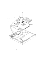
a 3 9 8 7 2 EXPLODED VIEW a b 12 10 11 6 5 1 14 15 13 4 c - 19 - - Dell 1800FP | Service Manual - Page 20
LCD(LIQUID CRYSTAL DISPLAY), LM181E06-A4M1 LG PHILPS TFT COLOR SXGA 18.1" LVDS SMM BACK COVER ASSEMBLY, 3808TKL030A TILT SWIVEL ASSEMBLY PWB(PCB) ASSEMBLY, SUB, LD803H CONTROL TOTAL BRAND CONNECTOR ASSEMBLY, 30P H-H 100MM UL20276 PANEL LINK LB886F INVERTER ASSEMBLY, ALPS KUBNKM045A 6-LAMPS,18" DELL - Dell 1800FP | Service Manual - Page 21
REPLACEMENT PARTS LIST CAUTION: BEFORE REPLACING ANY OF THESE COMPONENTS, READ CAREFULLY THE SAFETY PRECAUTIONS IN THIS MANUAL. * NOTE : S SAFETY Mark AL ALTERNATIVE PARTS *S *AL LOC. NO. PART NO. MAIN BOARD CAPACITORS DATE: 2002. 05. 14. DESCRIPTION / SPECIFICATION C1 C106 C107 C151 C160 C161 - Dell 1800FP | Service Manual - Page 22
MOTOROLA SOT23 30 MMBD301LT1 TP MOTOROLA SOT23 30 MMBD301LT1 TP MOTOROLA SOT23 30 MMBD301LT1 TP MOTOROLA SOT23 30 *S *AL LOC. NO. PART NO. DATE: 2002. 05. 14. DESCRIPTION / SPECIFICATION D701 D702 D703 D704 D730 D731 D732 D733 D734 D735 D736 D737 D738 D739 D740 D741 D742 D743 D744 D745 D746 D747 - Dell 1800FP | Service Manual - Page 23
D.R/TP 2200 OHM 1/10 W 5% 1608 R/TP 0 OHM 1/10 W 5% 1608 R/TP 0 1/10W P-TYPE TAPPING 0 1/10W P-TYPE TAPPING 0 OHM 1/10 W 5% 1608 R/TP 0 OHM 1/10 W 5% 1608 R/TP *S *AL LOC. NO. PART NO. DATE: 2002. 05. 14. DESCRIPTION / SPECIFICATION R401 R402 R404 R405 R406 R501 R502 R505 R508 R511 R512 R513 R514 - Dell 1800FP | Service Manual - Page 24
TYPE TAPPING 0 1/10W P-TYPE TAPPING 0 1/10W P-TYPE TAPPING 0 1/10W P-TYPE TAPPING 0 1/10W P-TYPE TAPPING 0 1/10W P-TYPE TAPPING 0 1/10W P-TYPE NO. PART NO. DATE: 2002. 05. 14. DESCRIPTION / SPECIFICATION RA238 30PPM 20P POWER BOARD C901 C902 SA BULK PCX2 335 224K KMF 18*40 SYE / SWE 400V 120UF - Dell 1800FP | Service Manual - Page 25
DATE: 2002. 05. 14. DESCRIPTION / SPECIFICATION R914 R917 R918 R920 R921 R923 R924 R925 (7.0) 5% TA52 20 1/4W(3 5% TA52 EER3016 340UH V-10PIN LB886F SI TP8D13 DAEWOO +/- 15% 110/220V CONTROL BOARD C1 C2 LED1 R1 R2 R3 R4 R5 R6 R7 R8 SW1 SW2 SW3 SW4 SW5 SW6 SW7 SW8 0CK104CK56A 0CK104CK56A - Dell 1800FP | Service Manual - Page 26
Serial I/F GENESIS 292P SDRAM/I/F Anolog RGB Digital TMDS Input Video YUV [8-bits] Triple ADC TMDS RX Host Interface Microprocessor Frame Panel I/F [48-bits] Output Control SYSTEM BLOCK DIAGRAM Anolog RGB DVI Composite S-Video Video Decoder Frame Buffer (SDRAM/SGRAM) gm5020 Output to LCD - Dell 1800FP | Service Manual - Page 27
FUNCTION Pin Name A0, A1, A2 SDA SCL WP Vcc Vss Function Device Adress Inputs Serial Data/Address Serial Clock Write Protect +1.8V to + 6.0V power Supply Ground SCL A0 A1 A2 STATE COUNTERS SLAVE ADDRESS COMPARATORS DATA IN STORAGE HIGH VOLTAGE/ TIMING CONTROL - Dell 1800FP | Service Manual - Page 28
1. GM5020 - Dell 1800FP | Service Manual - Page 29
2. MEMORY - Dell 1800FP | Service Manual - Page 30
3. LVDS - Dell 1800FP | Service Manual - Page 31
4. MICOM - Dell 1800FP | Service Manual - Page 32
5. DC/DC - Dell 1800FP | Service Manual - Page 33
6. CONNECTOR - Dell 1800FP | Service Manual - Page 34
7. CONTROL KEY - Dell 1800FP | Service Manual - Page 35
8. POWER
-
 1
1 -
 2
2 -
 3
3 -
 4
4 -
 5
5 -
 6
6 -
 7
7 -
8
-
9
-
10
-
11
-
12
-
13
-
14
-
15
-
16
-
17
-
18
-
19
-
20
-
21
-
22
-
23
-
24
-
25
-
26
-
27
-
28
-
29
-
30
-
31
-
32
-
33
-
34
-
35
 |
 |

COLOR MONITOR
SERVICE MANUAL
CAUTION
BEFORE SERVICING THE UNIT,
READ THE
SAFETY PRECAUTIONS
IN THIS MANUAL.
CHASSIS NO. :
CL-29
FACTORY MODEL:
LD803H
MODEL: 1800FP