Dell 1800FP Service Manual - Page 10
Adjustment - manual
 |
View all Dell 1800FP manuals
Add to My Manuals
Save this manual to your list of manuals |
Page 10 highlights
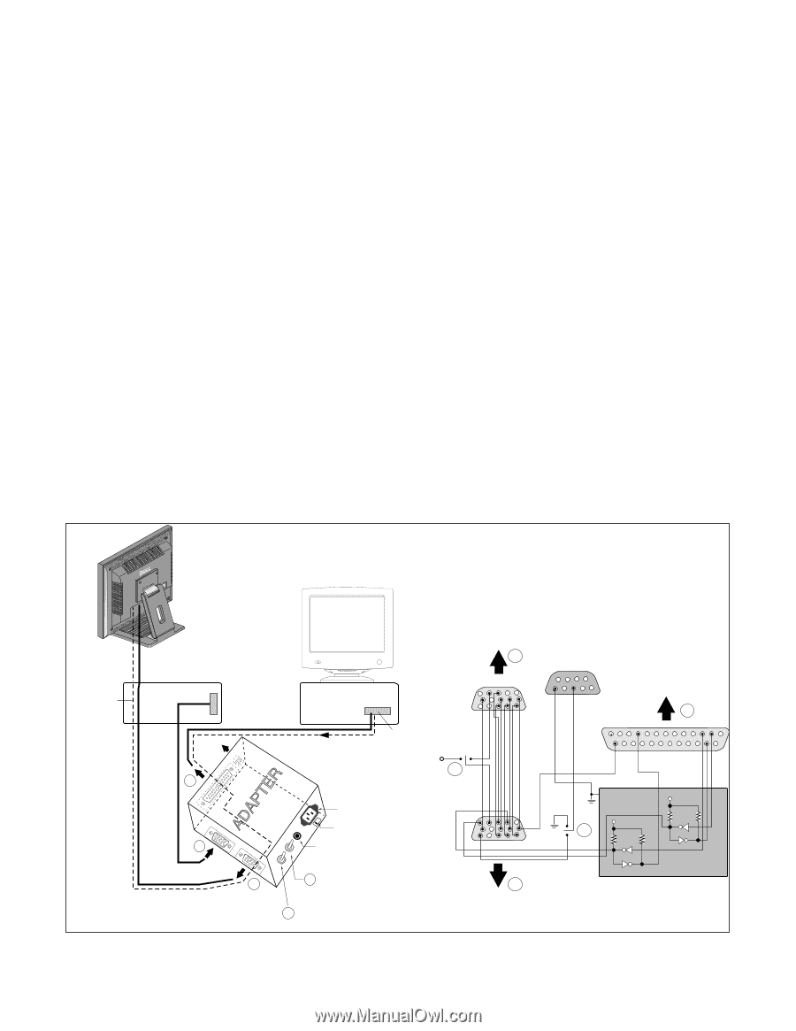
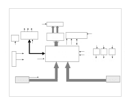
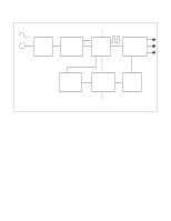
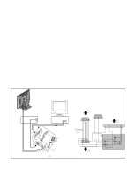
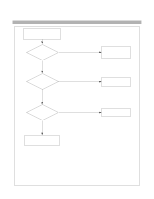
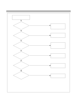
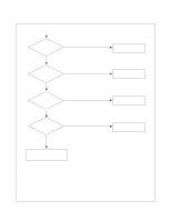
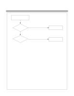
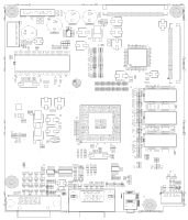
ADJUSTMENT All adjustment are thoroughly checked and corrected when the monitor leaves the factory, but sometimes several minor adjustment may be required. Adjustment should be following procedure and after warming up for a minimum of 10 minutes. • Alignment appliances and tools. - IBM compatible PC - Programmable Signal Generator. (eg. VG-819 made by Astrodesign Co.) - E(E)PROM with each mode data saved. 1. Adjustment Start 1) Display any pattern at any Mode. 2) Run alignment program for LD803H on the IBM compatible PC. 3) Select EEPROM → ALL INIT command and Enter. 4) This will make all data to default state. 5) Select COMMAND → PRESET START command and Enter. 2. Adjustment for White Balance 1) Display Black pattern at SXGA/60Hz. 2) Set External Bright to MAX position and Contrast to MAX Position. 3) Select PRESET START → BIAS CAL command and Enter. 4) No attempt to manually adjust, BIAS data is automatically adjusted and saved to the EEPROM. 5) Display Full White pattern at SXGA/60Hz. 6) Select DRIVE CAL command and Enter. 7) 9300K are automatically adjusted and saved to the EEPROM. 8) Select PRESET EXIT command and Enter. 3. Adjustment for EDID 1) Use this procedure only when there is some probelm on EDID data. 2) Connect the D-sub cable. 3) Select EEPROM → EDID(A) WR command and Enter. 4) DVI to D-sub cable. 5) Select EEPROM → EDID(D) WR command and Enter. Video Signal Generator Control Line IBM 15 Compatible PC 10 5 Not used RS232C PARALLEL PORT OFF ON 5V F C PARALLEL VGS A MONITOR B V-SYNC ST POWER Power inlet (required) 220 Power Select Switch (110V/220V) Power LED E ST Switch F V-Sync On/Off Switch (Switch must be ON.) Figure 1. Cable Connection A 9 5 11 6 1 6 1 13 25 C 1 14 ON E OFF 5V 4.7K 5V 4.7K 4.7K 74LS06 74LS06 B - 10 -
-
 1
1 -
2
-
3
-
4
-
 5
5 -
 6
6 -
 7
7 -
 8
8 -
 9
9 -
 10
10 -
 11
11 -
 12
12 -
 13
13 -
 14
14 -
 15
15 -
16
-
17
-
18
-
19
-
20
-
21
-
22
-
23
-
24
-
25
-
26
-
27
-
28
-
29
-
30
-
31
-
32
-
33
-
34
-
35
 |
 |