Dell Alienware M17X R3 Service Manual (English Only) - Page 47
Replace the processor heat-sink fan see Replacing the Processor
 |
View all Dell Alienware M17X R3 manuals
Add to My Manuals
Save this manual to your list of manuals |
Page 47 highlights
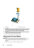
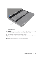
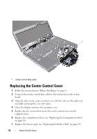
2 Align the pin-1 corner of the processor module with the pin-1 corner of the ZIF socket, then place the processor module. NOTE: The pin-1 corner of the processor module has a triangle that aligns with the triangle on the pin-1 corner of the ZIF socket. When the processor module is properly seated, all four corners are aligned at the same height. If one or more corners of the module are higher than the others, the module is not seated properly. CAUTION: To avoid damage to the processor module, hold the screwdriver perpendicular to the processor module when turning the cam screw. 3 Tighten the ZIF socket by turning the cam screw clockwise to secure the processor module to the system board. 4 Replace the processor heat-sink (see "Replacing the Processor Heat-Sink" on page 42). 5 Replace the processor heat-sink fan (see "Replacing the Processor Heat-Sink Fan" on page 38). 6 Replace the compartment door (see "Replacing the Compartment Door" on page 16). 7 Replace the battery pack (see "Replacing the Battery Pack" on page 14). CAUTION: Before turning on the computer, replace all screws and ensure that no stray screws remain inside the computer. Failure to do so may result in damage to the computer. Processor Module 47
-
 1
1 -
2
-
3
-
4
-
5
-
6
-
7
-
8
-
9
-
10
-
11
-
12
-
13
-
14
-
15
-
16
-
17
-
18
-
19
-
20
-
21
-
22
-
23
-
24
-
25
-
26
-
27
-
28
-
29
-
30
-
31
-
32
-
33
-
34
-
35
-
36
-
37
-
38
-
39
-
40
-
41
-
 42
42 -
 43
43 -
 44
44 -
 45
45 -
 46
46 -
 47
47 -
 48
48 -
 49
49 -
 50
50 -
 51
51 -
 52
52 -
53
-
54
-
55
-
56
-
57
-
58
-
59
-
60
-
61
-
62
-
63
-
64
-
65
-
66
-
67
-
68
-
69
-
70
-
71
-
72
-
73
-
74
-
75
-
76
-
77
-
78
-
79
-
80
-
81
-
82
-
83
-
84
-
85
-
86
-
87
-
88
-
89
-
90
-
91
-
92
-
93
-
94
-
95
-
96
-
97
-
98
-
99
-
100
-
101
-
102
-
103
-
104
-
105
-
106
-
107
-
108
-
109
-
110
 |
 |