Dell C2660dn Dell Color Laser Printer Quick Reference Guide - Page 1
Dell C2660dn Manual
 |
View all Dell C2660dn manuals
Add to My Manuals
Save this manual to your list of manuals |
Page 1 highlights
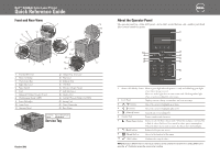
Dell™ C2660dn Color Laser Printer Quick Reference Guide Front and Rear View 1 14 12 13 11 10 9 15 16 2 3 8 7 5 6 1 Transfer Belt Unit 2 Drum Cartridges 3 Waste Toner Box 4 Right Side Cover 5 Power Switch 6 Tray1 7 Optional 550-Sheet Feeder (Tray2) 8 Multipurpose Feeder (MPF) 9 Toner Cartridges 10 Front Cover 11 Operator Panel 22 4 21 20 19 17 18 12 Output Tray Extension 13 Top Cover 14 Ethernet Port 15 USB Port 16 Wireless Adapter Socket 17 Left Side Cover 18 Duplex Unit 19 2nd Belt Transfer Roller (2nd BTR) 20 Fusing Unit 21 Power Connector 22 Rear Cover Service Tag Express Service Code xxxxxxx 000 000 000 00 Service Tag October 2013 About the Operator Panel The operator panel has a 4-line LCD panel, a status LED, control buttons, and a number pad, which allows you to control the printer. 1 2 10 3 4 4 9 3 8 5 6 7 1 Status LED (Ready / Error) Shows a green light when the printer is ready and a blinking green light when data is being received. Shows an amber light when an error occurs and a blinking amber light when an unrecoverable print error occurs. 2 LCD Panel Displays various settings, instructions, and error messages. 3 button Moves the cursor or highlight up or down. 4 button Moves the cursor or highlight right or left. 5 (Cancel) button Cancels active or pending jobs. 6 Number Pad Enters numbers and characters. 7 (Power Saver) button Enters or exits the Power Saver mode. When the machine is not used for a while, it enters the Power Saver mode to reduce power consumption. When the Power Saver mode is active, the Power Saver button blinks. 8 (Back) button Returns to the previous screen. 9 (Menu) button Moves to the top level of the menu. 10 (Set) button Confirms the entry of values. NOTE: Moving to a different menu or returning to a previous screen cancels the current entry or setting. Make sure to press the (Set) button to save the current entry or setting.
-
 1
1 -
 2
2
 |
 |
