Dell Force10 S25-01-GE-24V Installing the S25N and S25V Systems
Dell Force10 S25-01-GE-24V Manual
 |
View all Dell Force10 S25-01-GE-24V manuals
Add to My Manuals
Save this manual to your list of manuals |
Dell Force10 S25-01-GE-24V manual content summary:
- Dell Force10 S25-01-GE-24V | Installing the S25N and S25V Systems - Page 1
Installing S25N and S25V Systems December 15, 2008 100-00061-02 - Dell Force10 S25-01-GE-24V | Installing the S25N and S25V Systems - Page 2
of Conditions In the interest of improving internal design, operational function, and/or reliability, Force10 Networks reserves the right to make changes to products described in this document without notice. Force10 Networks does not assume any liability that may occur due to the use or application - Dell Force10 S25-01-GE-24V | Installing the S25N and S25V Systems - Page 3
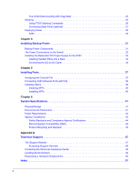
Contents Preface About this Guide 5 Information Symbols and Warnings 5 Related Publications 7 Chapter 1 System Fans and Airflow 16 Power 17 S25N 17 S25V 17 Power over Ethernet (PoE) Support 17 Storing Components 18 Tools Required 18 Chapter 3 Installing the Switch 19 Inserting Optional - Dell Force10 S25-01-GE-24V | Installing the S25N and S25V Systems - Page 4
Agency Certifications 44 Electromagnetic Compatibility (EMC 44 Product Recycling and Disposal 45 Appendix A Technical Support 47 The iSupport Website 47 Accessing iSupport Services 48 Contacting the Technical Assistance Center 49 Locating Serial Numbers 49 Requesting a Hardware Replacement - Dell Force10 S25-01-GE-24V | Installing the S25N and S25V Systems - Page 5
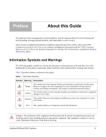
refer to the FTOS Configuration Guide for the S-Series for software configuration information and the FTOS Table 1 describes symbols contained in this guide. Table 1 Information Symbols Symbol Warning Description and qualified personnel only. Read this guide before installing and powering up this - Dell Force10 S25-01-GE-24V | Installing the S25N and S25V Systems - Page 6
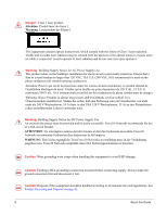
Supply Notice for DC Power Supply Use An external disconnect must be provided and be easily accessible. Force10 Networks recommends the use of a 60A circuit breaker. ATTENTION: Un interrupteur externe doit être laws and regulations. See Product Recycling and Disposal on page 45. 6 About this Guide - Dell Force10 S25-01-GE-24V | Installing the S25N and S25V Systems - Page 7
batteries usagees conformement aux instructions du fabricant. Note: Other cautionary statements appear in context elsewhere in this book. Related Publications The S25N and S25V run FTOS version 7.7.1.0 or greater. Refer to the following documents: • FTOS Configuration Guide for the S-Series • FTOS - Dell Force10 S25-01-GE-24V | Installing the S25N and S25V Systems - Page 8
8 About this Guide - Dell Force10 S25-01-GE-24V | Installing the S25N and S25V Systems - Page 9
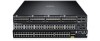
S25-01-GE-24T) and S25V (Cat# S25-01-GE-24V) models of the S-Series are high performance, low cost, stackable, Layer 2 switch/Layer 3 routers that support ). See Supplying Power on page 29. The S25V can also use the Force10 470W Redundant DC Power Supply (see Chapter 4, Installing Backup Power, on - Dell Force10 S25-01-GE-24V | Installing the S25N and S25V Systems - Page 10
fn00158s25V Figure 2 The S25V Rear View Label (Part #, Serial #, MAC Address, Bar Code, FRU #) 10-Gigabit Modules or Stacking Modules (optional) DC Power 11.5 FG -48V RTN Current -48V Sharing 28 27 26 25 Ethernet Port Numbers 25 to 28, Right to Left Ground Connector AC Power - Dell Force10 S25-01-GE-24V | Installing the S25N and S25V Systems - Page 11
power allocation controll available through the CLI. The optional Force10 470W DC Redundant Power Supply can be attached in current-sharing mode to provide up to 940W (790W of PoE). • Supports up to 16384 MAC address entries supported with hardware-assisted aging • Stackable switch features • 19 - Dell Force10 S25-01-GE-24V | Installing the S25N and S25V Systems - Page 12
options, see: • The CLI Basics and BOOT_USER chapters in the FTOS Command Reference for the S-Series • The Configuration Fundamentals and Getting Started chapters in the FTOS Configuration Guide for the S-Series LED Displays As shown in Figure 1 on page 9, the front panel of the switch contains - Dell Force10 S25-01-GE-24V | Installing the S25N and S25V Systems - Page 13
Table 3 describes the LED status indicators on the left side of the front panel. Table 3 Status Panel LED Display Label LED Color OK AC1 (on S25N) AC (on S25V) XFP25* XFP26* STACK ID Green Off Green Blinking Amber Green Amber Off Green Blinking Green Off Green Blinking Green Off Green Alarm - Dell Force10 S25-01-GE-24V | Installing the S25N and S25V Systems - Page 14
14 System Overview - Dell Force10 S25-01-GE-24V | Installing the S25N and S25V Systems - Page 15
Chapter 2 Site Preparation This chapter describes requirements and procedures to install your S25N or S25V system, in the following topics: • Site Selection • Cabinet Placement on page 16 • Rack Mounting on page 16 • Fans and Airflow on page 16 • Power on page 17 • Storing Components on page 18 • - Dell Force10 S25-01-GE-24V | Installing the S25N and S25V Systems - Page 16
rack must be grounded to the same ground point used by the power service in your area. The ground path must be permanent. Fans and messages. For details, see the logging chapters of the Command Reference and Configuration Guide. In a stack, each unit has its own temperature monitoring and control - Dell Force10 S25-01-GE-24V | Installing the S25N and S25V Systems - Page 17
of 940W. The 470W PSU is oversized in order to support PoE, as described next. See also Backup Power Components . If the external 470W DC Force10 Redundant Power Supply (catalog # S50-01-PSU-V) is attached to the a brief introduction in this guide to the PoE commands, see Connecting S25V Ethernet Ports - Dell Force10 S25-01-GE-24V | Installing the S25N and S25V Systems - Page 18
Storing Components If you do not install your system and components immediately, Force10 Networks recommends that you properly store the system and all optional components until you are ready to install them. Follow these storage guidelines: • Storage temperature - Dell Force10 S25-01-GE-24V | Installing the S25N and S25V Systems - Page 19
S25N or S25V systems, Force10 Networks recommends that you complete Stacking) The S25N (catalog name S25-01-GE-24T) and S25V (catalog name S25-01-GE-24V) have two expansion slots in the Catalog Name S50-01-10GE-2P S50-01-10GE-2C S50-01-12G-2S S50-01-24G-1S The system supports the modules inserted - Dell Force10 S25-01-GE-24V | Installing the S25N and S25V Systems - Page 20
page 46 or the installation instructions that come with the transceiver). The CX4 module (catalog name S50-01-10GE-2C) ports do XFP-1CX4) in the slot. However, an XFP port does not support the use of the cx4-cable-length command, discussed next. Do not Configuration Guide. 20 Installing the Switch - Dell Force10 S25-01-GE-24V | Installing the S25N and S25V Systems - Page 21
through each bracket and onto the rack post. Figure 4 Two-post (Front-mounted) Rack-mounting AC STACK ID XFP25 XFP26 Alarm DC 27 P28 S50-01-GE-24V fn00147aS25N Installing S25N and S25V Systems 21 - Dell Force10 S25-01-GE-24V | Installing the S25N and S25V Systems - Page 22
secure the mounting bracket with three screws. Figure 5 Four-Post Rack-mounting with Threaded Rails AC STACK ID XFP25 XFP26 Alarm DC 27 P28 S50-01-GE-24V fn00146s25N 2 Insert the unit into the rack, and secure the unit to the front post with two screws. Then secure it to the rear posts - Dell Force10 S25-01-GE-24V | Installing the S25N and S25V Systems - Page 23
the length with the four screws. Figure 7 Four-post Rack-mounting with Threaded Rails fn00148S25N AC STACK ID XFP25 XFP26 Alarm DC 27 P28 S50-01-GE-24V Four-Post Rack-mounting with Cage Nuts Installing S25N and S25V Systems 23 - Dell Force10 S25-01-GE-24V | Installing the S25N and S25V Systems - Page 24
the screws. Figure 8 Four-Post Rack-mounting with Cage Nuts Top View of Brackets AC STACK ID XFP25 XFP26 Alarm DC 27 P28 S50-01-GE-24V Align brackets fn00147f_s25N 2 Align and secure the adjustable bracket onto the rear bracket. 3 Insert the unit into the rear of the rack. Position and - Dell Force10 S25-01-GE-24V | Installing the S25N and S25V Systems - Page 25
bracket flange and each rack post. Figure 10 Four-Post Rack-mounting with Cage Nuts AC STACK ID XFP25 XFP26 Alarm DC 27 P28 S50-01-GE-24V fn00147d_s25N 5 Align the rack filler panel to the rear bracket and rack posts. Secure by inserting two screws into the hole in the filler panel - Dell Force10 S25-01-GE-24V | Installing the S25N and S25V Systems - Page 26
order in which they come online. So, when setting up a new stack, you should have no trouble forcing the identification of the management unit and unit IDs by methodically supplying power to the units in and the S-Series Stacking chapter in the FTOS Configuration Guide. 26 Installing the Switch - Dell Force10 S25-01-GE-24V | Installing the S25N and S25V Systems - Page 27
up. You can use either a ring topology or cascade topology connection (see Figure 12). Use the special stacking cables to connect them. Force10 recommends that you mount the switches before you make your stack port connections. Figure 12 Switch Stacking Topologies (showing dual-port modules) Ring - Dell Force10 S25-01-GE-24V | Installing the S25N and S25V Systems - Page 28
Stack Port A Stack Port B Note: Figure 14 and Figure 15 and these instructions use "Stack Port A" and "Stack Port B" for clarifying the connections, but the modules are not labeled. Connecting Three Switches Force10 recommends the ring topology, as outlined above (Figure 12 on page 27), because - Dell Force10 S25-01-GE-24V | Installing the S25N and S25V Systems - Page 29
AC only, DC only, or using both AC and DC sources. In addition, Force10 provides, as an option, an external 470W DC Redundant Power Supply Unit (PSU), cables to connect to the power source. Cables must be sized for 11.5 A service at no more than -48 VDC input (per NEC in the United States; - Dell Force10 S25-01-GE-24V | Installing the S25N and S25V Systems - Page 30
30 Installing the Switch - Dell Force10 S25-01-GE-24V | Installing the S25N and S25V Systems - Page 31
60/40). If you connect the 470W DC Force10 Redundant Power Supply Unit (PSU) to the external S-Series power supplies are field serviceable. If an internal power supply fails, supporting both the switch itself and the PoE feature. The PSU kit includes: • The AC/DC rectifier (catalog name S50-01 - Dell Force10 S25-01-GE-24V | Installing the S25N and S25V Systems - Page 32
AC and DC connections are made and able to supply power, the switch will only utilize them in load-sharing mode. If you attach the Force10 470W DC Redundant PSU, and you want to supply maximum PoE power, you connect the blue DC Current Sharing lead so that the internal and - Dell Force10 S25-01-GE-24V | Installing the S25N and S25V Systems - Page 33
includes rack-mounting hardware, an AC cable, and a cable to connect to the DC power leads on the S25V. The power supply is oversized to support the Power over Internet (PoE) feature, too large to install in the S50 External Power Shelf (EPS). Instead, to install the PSU in a rack, complete - Dell Force10 S25-01-GE-24V | Installing the S25N and S25V Systems - Page 34
Inserting Tandem PSUs into a Rack To install two PSUs in tandem (side-by-side) in a rack, follow these steps: Step 1. 2. Task Using a #2 Phillips screwdriver, attach the supplied extended rack ears to the outside, front sides of the two PSUs. As shown in Figure 20, the long side of the rack ear - Dell Force10 S25-01-GE-24V | Installing the S25N and S25V Systems - Page 35
Figure 21 DC-DC Cable for S25V PSU Follow the steps below to connect the S25V switch to the 470W PSU. Step 1. Task With the switch unplugged from AC power, connect the individual leads of the DC-to-DC cable to the DC terminal lugs of the switch (Figure 22), with a #2 Philips screwdriver. Connect - Dell Force10 S25-01-GE-24V | Installing the S25N and S25V Systems - Page 36
Step 2. Task Insert the plastic plug of the DC-to-DC cable into the receptacle on the lower left side of the PSU (Figure 23). Note that one of the three leads on the plug has a trapezoidal key , which goes in the receptacle that is toward the center of the PSU. The key is not strong enough to - Dell Force10 S25-01-GE-24V | Installing the S25N and S25V Systems - Page 37
Chapter 5 Installing Ports This chapter contains these major sections: • Accessing the Console Port on page 37 • Connecting S25V Ethernet Ports with PoE on page 38 • Installing Optics on page 39 Accessing the Console Port Connect the RJ-45/DB-9 adapter that is shipped with the system to the RJ- - Dell Force10 S25-01-GE-24V | Installing the S25N and S25V Systems - Page 38
power for other uses, and the default PoE configuration limits PoE power to 288 watts. As described in Power over Ethernet (PoE) Support on page 17, you can raise that chapters of the FTOS Configuration Guide for the S-Series and the FTOS Command Reference for the S-Series. 38 Installing Ports - Dell Force10 S25-01-GE-24V | Installing the S25N and S25V Systems - Page 39
the switch is running. Caution: Before connecting a transceiver to a source, check the receive power of the transceiver with an optical power meter. Generally, Force10 specified optics are not to be subjected to receive power higher than that stipulated by the optic specification. If the optic is - Dell Force10 S25-01-GE-24V | Installing the S25N and S25V Systems - Page 40
the slot. An XFP port does not support the use of the cx4-cable-length command. For details, see Inserting Optional Modules (10-Gigabit or Stacking) on page 19 in Chapter 3, Installing the Switch. For enabling ports with FTOS, see the FTOS Configuration Guide for the S-Series. 40 Installing Ports - Dell Force10 S25-01-GE-24V | Installing the S25N and S25V Systems - Page 41
Chapter 6 System Specifications Physical Design Parameter Weight (with only factory-installed components) Height Width Depth Rack clearance required Specifications 19.5 pounds (approx.) (8.85 kg) 1.73 inches (4.4 cm) 17.32 inches (44 cm) (19" rack-mountable) 16.73 inches (42.5 cm) (standard 1 - Dell Force10 S25-01-GE-24V | Installing the S25N and S25V Systems - Page 42
S25V contain no user-serviceable parts. They contain a lithium clock battery that is not field-serviceable. For details on installed and used in accordance to the instructions, it may cause harmful interference to order to meet FCC emission limits. Force10 Networks is not responsible for any - Dell Force10 S25-01-GE-24V | Installing the S25N and S25V Systems - Page 43
in a domestic environment, radio disturbance may arise. When such trouble occurs, the user may be required to take corrective actions. Danger: AC Power cords are for use with Force10 Networks equipment only. Do not use Force10 Networks AC power cords with any unauthorized hardware. Installing S25N - Dell Force10 S25-01-GE-24V | Installing the S25N and S25V Systems - Page 44
Differences • EN 60950-1, 1st Edition • EN 60825-1, 1st Edition • EN 60825-1 Safety of Laser Products-Part 1: Equipment Classification Requirements and User's Guide • EN 60825-2 Safety of Laser Products-Part 2: Safety of Optical Fibre Communication Systems • FDA Regulation 21CFR 1040.10 and 1040.11 - Dell Force10 S25-01-GE-24V | Installing the S25N and S25V Systems - Page 45
longer needed. Force10 offers a variety of product return programs and services in several Force10 product recycling offerings, see the WEEE Recycling instructions on iSupport at: https://www.force10networks.com/CSPortal20/Support/WEEEandRecycling.pdf. For more information, contact the Force10 - Dell Force10 S25-01-GE-24V | Installing the S25N and S25V Systems - Page 46
the environment and human health due to the potential presence of hazardous substances. For proper collection and treatment, contact your local Force10 Networks representative. Figure 29 The European WEEE symbol For California: Perchlorate Material - Special handling may apply. See: http://www.dtsc - Dell Force10 S25-01-GE-24V | Installing the S25N and S25V Systems - Page 47
Center (TAC) cases. Force10 iSupport provides integrated, secure access to these services. The i-Support website (see Figure 30, below) (http://www.force10networks.com/support/) contains a publicly available interface that includes access to techtips, white papers, and user manuals. After you get an - Dell Force10 S25-01-GE-24V | Installing the S25N and S25V Systems - Page 48
The screenshot above shows the Support Policies section of iSupport. The Support Guide, available on that page, details the types of information and services that you can access through iSupport and through various types of support contracts. Accessing iSupport Services The URL for iSupport is - Dell Force10 S25-01-GE-24V | Installing the S25N and S25V Systems - Page 49
Assistance Center How to Contact Force10 TAC Information to Submit When Opening a Support Case Managing Your Case Downloading Software Updates Technical Documentation Contact Information Log in to iSupport at http://www.force10networks.com/support/, and select the Service Request tab. • Your name - Dell Force10 S25-01-GE-24V | Installing the S25N and S25V Systems - Page 50
support case. Open a support case by: • Using the Create Service Request form on the iSupport page (see Contacting the Technical Assistance Center, above). • Contacting Force10 show tech-support.) • Console captures showing the error messages • Console captures showing the troubleshooting steps taken - Dell Force10 S25-01-GE-24V | Installing the S25N and S25V Systems - Page 51
XFP-1CX4 (for CX4 XFP) 20, 40 catalog name S50-01-10GE-2C (CX4 module) 20 catalog name SA-01-PSU-V (external rectifier) 31 catalog name, S25N 19 catalog 26 show system stack-ports 26 show system stack-unit 26 show tech-support 50 stack-unit priority 26 stack-unit provision 26 stack-unit renumber 26 - Dell Force10 S25-01-GE-24V | Installing the S25N and S25V Systems - Page 52
E earth ground 16 electromagnetic noise 15 electrostatic discharge 18, 19 Emissions 44 Environmental Parameters 41 ESD 18, 19, 39, 40 Ethernet crossover cable 37 Ethernet ports 10 European compliance 43 European WEEE Directive 45 F fan replacement 16 fan speed 16 fans 11, 16 fans and ventilation 16 - Dell Force10 S25-01-GE-24V | Installing the S25N and S25V Systems - Page 53
hardware 50 RJ-45 installation 37 S S25N (Cat# S25-01-GE-24T) 9 S25N rear view 10 S25V (Cat# S25-01-GE-24V) 9 S25V front view 9 S25V PSU 33 S25V stack-ports command 26 show system stack-unit command 26 show tech-support command 50 SNMP traps 12 sound levels 41 Specifications Agency Compliance 42 - Dell Force10 S25-01-GE-24V | Installing the S25N and S25V Systems - Page 54
T Table of Contents 3 Tabletop Installation 21 Technical Assistance Center (TAC), contacting 47 Telcordia 41 temperature acceptable ambient range 41 fans and ventilation 16 relative humidity 18 storage 18 temperature warning message 16 temperature, operating 41 temperature, storage 41 terminal
-
 1
1 -
 2
2 -
 3
3 -
 4
4 -
 5
5 -
 6
6 -
 7
7 -
8
-
9
-
10
-
11
-
12
-
13
-
14
-
15
-
16
-
17
-
18
-
19
-
20
-
21
-
22
-
23
-
24
-
25
-
26
-
27
-
28
-
29
-
30
-
31
-
32
-
33
-
34
-
35
-
36
-
37
-
38
-
39
-
40
-
41
-
42
-
43
-
44
-
45
-
46
-
47
-
48
-
49
-
50
-
51
-
52
-
53
-
54
 |
 |

Installing S25N and S25V Systems
December 15, 2008
100-00061-02