Dell Force10 S50-01-GE-48T Installing S50N and S50V Systems
Dell Force10 S50-01-GE-48T Manual
 |
View all Dell Force10 S50-01-GE-48T manuals
Add to My Manuals
Save this manual to your list of manuals |
Dell Force10 S50-01-GE-48T manual content summary:
- Dell Force10 S50-01-GE-48T | Installing S50N and S50V Systems - Page 1
Installing S50N and S50V Systems - Dell Force10 S50-01-GE-48T | Installing S50N and S50V Systems - Page 2
damage to hardware or loss of data if instructions are not followed. WARNING: A WARNING indicates a potential for property damage, personal injury, or death. Information in this publication is subject to change without notice. © 2010 Dell Force10. All rights reserved. Reproduction of these materials - Dell Force10 S50-01-GE-48T | Installing S50N and S50V Systems - Page 3
10 Ports 10 System Status 11 LED Displays 11 3 Site Preparations Site Selection 13 Cabinet Placement 13 Rack Mounting 14 Fans and Airflow 14 Power 14 S50N-DC 14 S50N and S50V 15 Power over Ethernet (PoE) Support 15 Storing Components 16 Tools Required 16 4 Installing the Switch - Dell Force10 S50-01-GE-48T | Installing S50N and S50V Systems - Page 4
Ports Accessing the Console Port 41 Connecting S50V Ethernet Ports with PoE 42 Installing Optics 43 Installing SFPs 43 Installing XFPs 44 7 Switch Specifications Chassis Physical Design 47 Environmental Parameters 48 Power Requirements 48 AC Power Requirements 48 DC Power Requirements 48 - Dell Force10 S50-01-GE-48T | Installing S50N and S50V Systems - Page 5
and desk mounting the S50V or S50N switches (and related models, such as S50N-DC), inserting optional modules, and connecting to a power source. Except where noted, descriptions and instructions in this guide apply to all variants of these switches. After you have completed the hardware installation - Dell Force10 S50-01-GE-48T | Installing S50N and S50V Systems - Page 6
als 240 V Wechselstrom, 10 A (bzw. in den USA 120 V Wechselstrom, 15 A) an den Phasenleitern (allen stromführenden Leitern) verwendet wird. WARNING: Building Supply Notice for DC Power Supply Use. An external disconnect must be provided and be easily accessible. Dell Force10 recommends the use of - Dell Force10 S50-01-GE-48T | Installing S50N and S50V Systems - Page 7
CD-ROM contains the S-Series hardware guides and the FTOS and SFTOS files listed above, respectively, except for the Release Notes. The CD-ROMs also have: • MIBs: Files for all SNMP MIBs supported by the software • Data sheets: Links to Dell Force10 product data sheets NOTE: Documentation CD - Dell Force10 S50-01-GE-48T | Installing S50N and S50V Systems - Page 8
www.dell.com | support.dell.com 8 | About this Guide - Dell Force10 S50-01-GE-48T | Installing S50N and S50V Systems - Page 9
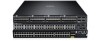
Alarm AC DC XFP49 XFP51 XFP51 XFP52 Catalog # (S50-01-GE-48T-V) Link/Active Indicator LEDs (SFP Ports 45-48) Stack ID AC XFP49 XFP50 Alarm DC 51 P52 S50-01-GE-48T-V fn00157s50V RJ-45 Console Port Ethernet Ports (10/100/1000) Shared 10/100/1000 Ports (45-48) SFP Ports (45-48) Figure - Dell Force10 S50-01-GE-48T | Installing S50N and S50V Systems - Page 10
in SFTOS • Back-pressure support at half-duplex, IEEE 802.3x flow control at full duplex • Extensive LED system with per-port LEDs Ports • 48 fixed 10/100/1000 Mbps auto-sensing and auto-MDIX RJ45 ports, up to 15.4W PoE each • Four ports capable of using 10/100/1000 Base-T or 1000 Base-X using auto - Dell Force10 S50-01-GE-48T | Installing S50N and S50V Systems - Page 11
front of the switch) Green - Link up on this port Blinking Green - Activity, transmitting or receiving packet in link up state Off - No Link detected at this port * The LEDs for a 10/100/1000 port numbered 45 through 48 are inactive if the shared SFP port (also labeled 45 through 48) is enabled - Dell Force10 S50-01-GE-48T | Installing S50N and S50V Systems - Page 12
www.dell.com | support.dell.com NOTE: As suggested by the footnote above, the fiber SFP ports have priority over the four 10/100/1000 ports with the same number. The following table describes the LED status indicators on the left side of the front panel. Table 2-2. Status Panel LED Display - Dell Force10 S50-01-GE-48T | Installing S50N and S50V Systems - Page 13
• Power on page 14 • Storing Components on page 16 • Tools Required on page 16 For detailed switch specifications, refer to Chapter , Switch Specifications, on page 47. NOTE: Install the switch into a rack or cabinet before installing any optional components. Site Selection Make sure that the area - Dell Force10 S50-01-GE-48T | Installing S50N and S50V Systems - Page 14
www.dell.com | support.dell.com Rack Mounting When you prepare your equipment rack, ensure that the rack is earth ground. The equipment rack must be grounded to the same ground point used by the power service in your area. The ground path must be permanent. Fans and Airflow Ventilation is side-to- - Dell Force10 S50-01-GE-48T | Installing S50N and S50V Systems - Page 15
they act in roughly a 60%/40% load-sharing mode. On the S50V, when the Dell Force10 470W DC Backup Power Supply is connected to the Current Sharing connection on the S50V DC terminal block, the switch uses the DC and AC power supplies in current-sharing (load-sharing plus additive) mode, so that the - Dell Force10 S50-01-GE-48T | Installing S50N and S50V Systems - Page 16
www.dell.com | support.dell.com The total PoE power budget for the switch is between 320W and 790W, depending on the power sources available. If the external 470W Redundant Power Supply (catalog # S50-01-PSU-V) from Dell Force10 is attached to the Current Sharing terminal (see Chapter , Installing - Dell Force10 S50-01-GE-48T | Installing S50N and S50V Systems - Page 17
when handling the switch and its components. See other relevant cautions in the Preface. Inserting Optional Modules (10-Gigabit or Stacking) The S50V (catalog number S50-01-GE-48T-V) and S50N (catalog number S50-01-GE-48T-AC for ACpowered version of S50N; S50-01-GE-48T-DC for S50N-DC) have two - Dell Force10 S50-01-GE-48T | Installing S50N and S50V Systems - Page 18
instructions that come with the transceiver. CAUTION: You can connect a CX4 cable to an XFP port through a CX4 XFP converter (catalog number GP- XFP-1CX4) in the slot. However, an XFP port does not support the use of the cx4-cable-length command, discussed next. CX4 module (catalog number S50-01 - Dell Force10 S50-01-GE-48T | Installing S50N and S50V Systems - Page 19
• Two-Post Rack Mounting • Four-Post Rack-mounting with Threaded Rails • Four-Post Rack-mounting with Cage Nuts Two-Post Rack Mounting The switch is shipped with the universal front-mounting brackets (rack ears) attached. Ensure that there is adequate clearance surrounding the rack to permit access - Dell Force10 S50-01-GE-48T | Installing S50N and S50V Systems - Page 20
www.dell.com | support.dell.com Step Task 1 Align the three screw holes of the adjustable rear mounting bracket with the three holes in the unit, and secure the chassis to the front post with two screws. Then secure it to the rear posts with two screws. fn00147s50V 20 | Installing the Switch - Dell Force10 S50-01-GE-48T | Installing S50N and S50V Systems - Page 21
to the chassis using the screws. Top View of Brackets 2 Align and secure the adjustable bracket onto the rear bracket. fn00147f_s50V Align brackets Installing the Switch | 21 - Dell Force10 S50-01-GE-48T | Installing S50N and S50V Systems - Page 22
www.dell.com | support.dell.com Step Task 3 Insert the chassis into the rear of the rack. Position and secure the chassis with two screws into . fn00147a_s50V(4post) 4 Position the cage nuts over the holes on each bracket flange and each rack post. fn00147d_s50V 22 | Installing the Switch - Dell Force10 S50-01-GE-48T | Installing S50N and S50V Systems - Page 23
order in which they come on-line. So, when setting up a new stack, you should have no trouble forcing the identification of the management unit and unit IDs by methodically supplying power to the units in your preferred down, in order to avoid stack management conflicts. Installing the Switch | 23 - Dell Force10 S50-01-GE-48T | Installing S50N and S50V Systems - Page 24
dell.com | support.dell.com Using SFTOS Stacking Commands If the switch is running SFTOS, the commands available to manage stacking are described in the Stacking chapters of the SFTOS Command Reference and the SFTOS Configuration Guide. You can execute clear config on the switch stack-ports command - Dell Force10 S50-01-GE-48T | Installing S50N and S50V Systems - Page 25
. Dell Force10 recommends that you mount the switches before you make your stack port connections. Figure 4-3. Switch Stacking Topologies (showing dual-port modules) Ring Topology Cascade Topology Switch 1 A B Switch 1 A B Switch 2 A B Switch 2 A B Switch 3 A B Switch 3 A B While - Dell Force10 S50-01-GE-48T | Installing S50N and S50V Systems - Page 26
-48V -48V Current RTN Sharing Stack Port A Stack Port B fn00151s25V1 NOTE: These diagrams and instructions use "Stack Port A" and "Stack Port B" for clarifying the connections, but the modules are not labeled. Connecting Three Switches Dell Force10 recommends the ring topology, as outlined above - Dell Force10 S50-01-GE-48T | Installing S50N and S50V Systems - Page 27
for providing power to the switch - AC only, DC only, or using both AC and DC sources. If you select the third choice - AC and DC - the switch will only use the DC source after the AC source fails. In addition, Dell Force10 provides, as an option, an external DC Redundant Power Supply Unit (PSU - Dell Force10 S50-01-GE-48T | Installing S50N and S50V Systems - Page 28
www.dell.com | support.dell.com front left of the switch (see Figure 2-2 on page 9); the left block is matched to the DC2 status LED. You must provide your own cables to connect to the power source. Cables must be sized for 11.5 A service at no more than -48VDC input (per NEC in the United States - Dell Force10 S50-01-GE-48T | Installing S50N and S50V Systems - Page 29
Unit (PSU) for the S50V supplies 470W DC, supporting both the switch itself and the PoE feature. The PSU kit includes: • The AC/DC rectifier (catalog number S50-01-PSU-V) • DC-to-DC cable to connect the PSU to the switch • AC cable to connect the PSU to the AC power source • PSU mounting hardware - Dell Force10 S50-01-GE-48T | Installing S50N and S50V Systems - Page 30
www.dell.com | support.dell.com The Power Connections on the Switch The S50V and S50N contain both AC and DC connections. An AC cable is supplied with the switch (see Supplying Power on page 27). You can connect one or both of the AC or DC inputs to power. If both connections are made and able to - Dell Force10 S50-01-GE-48T | Installing S50N and S50V Systems - Page 31
for a single unit. For a tandem installation, see Inserting Tandem S50V PSUs into a Rack on page 31. Step Task 1 Using a #2 Phillips screwdriver, attach the short sides of the rack ears to the front corners of the power supply with the supplied screws. Figure 5-3. Attaching Rack Ears to PSU 2 - Dell Force10 S50-01-GE-48T | Installing S50N and S50V Systems - Page 32
www.dell.com | support.dell.com Step Task 2 Join the two units with the supplied twinning plate (the small, flat, I-beam-shaped metal adapter with four screw holes), using two screws on each side of the plate through the front inside corners of the two switches. Orient the adapter with the - Dell Force10 S50-01-GE-48T | Installing S50N and S50V Systems - Page 33
1 With the switch unplugged from AC power, connect the individual leads of the DC-to-DC cable to the DC terminal lugs of the switch (Figure 5-8), with a #2 Phillips screwdriver. Connect the gray wire to FG, red to RTN, brown to -48V. If you connect the blue lead of the Dell Force10 PSU to Current - Dell Force10 S50-01-GE-48T | Installing S50N and S50V Systems - Page 34
www.dell.com | support.dell.com Step Task 2 Insert the plastic plug of the DC-to-DC cable into the receptacle on the lower left side of the DC Power DC Components • The External Power Shelf (EPS) (Catalog# SA-01-EPS) • S50/S50N Power Supply Unit (PSU) (Catalog# SA-01-PSU), an external AC-to-DC - Dell Force10 S50-01-GE-48T | Installing S50N and S50V Systems - Page 35
AC cable to the rectifier Installing the External Power Shelf (optional) Installing the PSU in a rack requires the External Power Shelf (EPS) (Catalog# SA-01-EPS), shown in Figure 5-10. It is a 2.5RU chassis that can house up to eight PSUs (for up to eight switches). Figure 5-10 below an S50. For - Dell Force10 S50-01-GE-48T | Installing S50N and S50V Systems - Page 36
www.dell.com | support.dell.com continue, as above. Figure 5-12 on page 36 shows the -Mounted (shown below an S50) Inserting an S50N PSU into the EPS The Power Supply Unit (PSU) that supports both the S50 and S50N is an optional, external AC/DC rectifier that provides 180W DC at 48V. 36 | - Dell Force10 S50-01-GE-48T | Installing S50N and S50V Systems - Page 37
right sides of the PSU. Connecting the DC-to-DC Cable for the S50N PSU The PSU kit for the S50 and S50N includes an AC cable and two DC-DC cables. One DC-DC cable is for the PSU-S50 connection (it has a plastic plug for connecting to the S50). The other DC-DC cable, for connecting the PSU to the - Dell Force10 S50-01-GE-48T | Installing S50N and S50V Systems - Page 38
www.dell.com | support.dell.com Figure 5-15. DC-DC Cable for S50N Follow the steps below to connect the switch to the PSU: Step Task 1 With the switch unplugged from AC power, connect the DC-DC plug to the switch. Connect the individual leads of the DC-to-DC cable to the DC terminal lugs of - Dell Force10 S50-01-GE-48T | Installing S50N and S50V Systems - Page 39
-DC Cable DC Power Module 3 Tighten the captive screws on the sides of the connector cable by turning them clockwise. 4 Insert your AC cable into the AC receptacle of the PSU. Ideally, you should connect that AC cable to an AC source separate from the AC connection made directly to the switch - Dell Force10 S50-01-GE-48T | Installing S50N and S50V Systems - Page 40
40 | Installing Backup Power www.dell.com | support.dell.com - Dell Force10 S50-01-GE-48T | Installing S50N and S50V Systems - Page 41
49 arm D 50 51 5 Set your initial console terminal settings to match the default console settings on the switch: • 9600 baud rate • No parity • 8 data bits • 1 stop bit • No flow control (console port only) After establishing a connection, you can modify the settings to match at each end of the - Dell Force10 S50-01-GE-48T | Installing S50N and S50V Systems - Page 42
dell.com | support.dell.com Step Task (continued) 4 If you use the console port to download software to the switch Connecting S50V Ethernet Ports with PoE The copper ports (1 through 48) in the The internal AC 470 watt power supply will limit PoE power to 320 watts if the switch requires power - Dell Force10 S50-01-GE-48T | Installing S50N and S50V Systems - Page 43
disable PoE for a specified switch in an S- Redundant Power Supply (catalog # S50-01-PSU-V), if Series stack. 10/100/1000 SFP optical transceivers. On the back of the switches, there are two bays that accept either stacking modules or 10GbE modules (CX4 or XFP). A 10GbE module contains two ports - Dell Force10 S50-01-GE-48T | Installing S50N and S50V Systems - Page 44
www.dell.com | support.dell.com WARNING: Electrostatic discharge (ESD) damage can occur if components are mishandled. Always wear an ESD-preventive wrist or heel ground strap when handling the switch and its components. Step Task 1 Position the SFP so it is in the upright position. (The SFP has - Dell Force10 S50-01-GE-48T | Installing S50N and S50V Systems - Page 45
) into the slot. An XFP port does not support the use of the cx4-cable-length command. For details, see Inserting Optional Modules (10-Gigabit or Stacking) on page 17. For enabling ports with FTOS, see the FTOS Configuration Guide. With SFTOS, see the SFTOS Configuration Guide or the S50V and S50N - Dell Force10 S50-01-GE-48T | Installing S50N and S50V Systems - Page 46
46 | Installing Ports www.dell.com | support.dell.com - Dell Force10 S50-01-GE-48T | Installing S50N and S50V Systems - Page 47
Power Requirements on page 48 • Agency Compliance on page 49 NOTE: The specifications in this chapter, unless otherwise noted, pertain to the S50V (catalog # S50-01-GE48T-V) and S50N (catalog # S50-01-GE-48T-AC for AC-powered version of S50N; catalog # S50-01-GE-48TDC for S50N-DC). Chassis Physical - Dell Force10 S50-01-GE-48T | Installing S50N and S50V Systems - Page 48
AC and DC inputs DC Power Requirements Parameter Nominal input voltage Maximum current draw Maximum system power consumption Specifications -48V to -54Vz S50N-DC: 3.6 A at -48 VDC S50V: 11.5 A @ -48VDC S50V: 470W (790W using current-sharing AC and DC inputs) S50N: 102W S50N-DC: 136W 48 | Switch - Dell Force10 S50-01-GE-48T | Installing S50N and S50V Systems - Page 49
switches contain a lithium battery. The switch contains no user-serviceable parts. For details on recycling the switch installed and used in accordance to the instructions, it may cause harmful interference to radio order to meet FCC emission limits. Dell Force10 is not responsible for any radio or - Dell Force10 S50-01-GE-48T | Installing S50N and S50V Systems - Page 50
www.dell.com | support.dell.com Japan: VCCI Compliance for Class A Equipment This is Class A product arise. When such trouble occurs, the user may be required to take corrective actions. WARNING: AC Power cords are for use with Dell Force10 equipment only. Do not use Dell Force10 AC power cords with - Dell Force10 S50-01-GE-48T | Installing S50N and S50V Systems - Page 51
of Laser Products-Part 1: Equipment Classification Requirements and User's Guide • EN 60825-2 Safety of Laser Products-Part 2: Safety Optical Fibre Communication Systems • FDA Regulation 21CFR 1040.10 and 1040.11 • IEC60950-1 1st Ed including EN 61000-4-3 Radiated Immunity Switch Specifications | 51 - Dell Force10 S50-01-GE-48T | Installing S50N and S50V Systems - Page 52
required by WEEE. For information on Dell Force10 product recycling offerings, see the WEEE Recycling instructions on iSupport at: http://www.force10networks.com/CSPortal20/Support/WEEEandRecycling.pdf. For more information, contact the Dell Force10 Technical Assistance Center (TAC) (see Contacting - Dell Force10 S50-01-GE-48T | Installing S50N and S50V Systems - Page 53
. To remove the lithium closed-cell clock battery (clearly visible towards the right rear of switch): 1 Insert a small, flat screw driver blade under the battery and in one of treatment, contact your local Dell Force10 representative. Figure 7-2. The European WEEE symbol Switch Specifications | 53 - Dell Force10 S50-01-GE-48T | Installing S50N and S50V Systems - Page 54
www.dell.com | support.dell.com For California: Perchlorate Material - Special handling may apply. See: http://www.dtsc.ca.gov/hazardouswaste/perchlorate California Code of Regulations Title 22, Division 4.5 Chapter 33. Best Management Practices for Perchlorate Materials. 54 | Switch Specifications - Dell Force10 S50-01-GE-48T | Installing S50N and S50V Systems - Page 55
manuals. After you get an account and log in, the available documentation expands to other types, including bug lists, error message decoder, release notes. You can even track your own Dell Force10 inventory. Accessing iSupport Services The URL for iSupport is http://www.force10networks.com/support - Dell Force10 S50-01-GE-48T | Installing S50N and S50V Systems - Page 56
Center How to Contact Dell Force10 TAC Information to Submit When Opening a Support Case Managing Your Case Downloading Software Updates Technical Documentation Contact Information Log in to iSupport at http://www.force10networks.com/support/, and select the Service Request tab. • Your name - Dell Force10 S50-01-GE-48T | Installing S50N and S50V Systems - Page 57
SFP DC support case. Open a support case by: • Using the Create Service Request form on the iSupport page (see Contacting the Technical Assistance Center on page 56). • Contacting Dell Force10 support.) • Console captures showing the error messages • Console captures showing the troubleshooting - Dell Force10 S50-01-GE-48T | Installing S50N and S50V Systems - Page 58
58 | Technical Support www.dell.com | support.dell.com - Dell Force10 S50-01-GE-48T | Installing S50N and S50V Systems - Page 59
53 battery, lithium 49 baud rate 41 brackets 10 C cabinet placement 13 cable, AC-to-AC 34 catalog name GP- XFP-1CX4 (for CX4 XFP) 45 catalog number GP- XFP-1CX4 (for CX4 XFP) 18 catalog number S50-01-10GE-2C (CX4 module) 18 catalog number S50-01-GE-48T-V (S50V) 17 catalog number, S50V 9, 17 catalog - Dell Force10 S50-01-GE-48T | Installing S50N and S50V Systems - Page 60
www.dell.com | support.dell.com E earth ground 14 electromagnetic noise 13 electrostatic discharge 16, 17 Emissions 51 Environmental Parameters 48 ESD 16, 17, 44 Ethernet crossover cable 41 Ethernet ports 15 European WEEE Directive 52 F fan replacement 14 fan speed 14 fans 10, 14 fans and - Dell Force10 S50-01-GE-48T | Installing S50N and S50V Systems - Page 61
10 rectifier 30, 34 recycling, switch 52 Redundant Power Supply Unit (PSU) 30, 31, 34 removing a unit from a stack 23, 24 removing battery 53 requesting replacement hardware 57 RJ-45 installation 41 S S50-01-GE-48T-AC (S50N catalog number) 17 S50-01-GE-48T-DC (S50N-DC catalog number) 17 S50-01-GE - Dell Force10 S50-01-GE-48T | Installing S50N and S50V Systems - Page 62
message 14 terminal server 41 terminal settings, console 41 Thermal Output, Maximum 48 Tools Required 16 topology cascade 25 ring 25 V ventilation 14 voltage 48 W Warning 6 AC Power Supply 6 DC Power Supply 6 WEEE 52, 53 Weight 47 width of chassis 47 62 | Index X XFP Installation 44 XFP LINK - Dell Force10 S50-01-GE-48T | Installing S50N and S50V Systems - Page 63
- Dell Force10 S50-01-GE-48T | Installing S50N and S50V Systems - Page 64
Printed in the U.S.A. www.dell.com | support.dell.com
-
 1
1 -
 2
2 -
 3
3 -
 4
4 -
 5
5 -
 6
6 -
 7
7 -
8
-
9
-
10
-
11
-
12
-
13
-
14
-
15
-
16
-
17
-
18
-
19
-
20
-
21
-
22
-
23
-
24
-
25
-
26
-
27
-
28
-
29
-
30
-
31
-
32
-
33
-
34
-
35
-
36
-
37
-
38
-
39
-
40
-
41
-
42
-
43
-
44
-
45
-
46
-
47
-
48
-
49
-
50
-
51
-
52
-
53
-
54
-
55
-
56
-
57
-
58
-
59
-
60
-
61
-
62
-
63
-
64
 |
 |

Installing S50N and
S50V Systems