Dell Force10 S50-01-GE-48T Quick Start Guide for the S50N and S50V Systems - Page 11
AC Power, chassis and then to the power source. Connect the plug to the AC receptacle
 |
View all Dell Force10 S50-01-GE-48T manuals
Add to My Manuals
Save this manual to your list of manuals |
Page 11 highlights
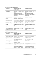
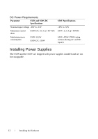
• All protective covers are in place. • Blank panels are installed if optional modules are not installed. NOTE: A US AC power cable is included in the shipping container for powering up an AC power supply. All other power cables must be ordered separately. CAUTION: Electrostatic discharge (ESD) damage can occur if components are mishandled. Always wear an ESD-preventive wrist or heel ground strap when handling the system and its components. CAUTION: The power supply cord is used as the main disconnect device; ensure that the socket-outlet is located/installed near the equipment and is easily accessible. AC Power For the S50V and S50N, to use AC only, connect the supplied AC power cord first to the switch (receptacle on the right as you face the PSU side of the chassis) and then to the power source. Connect the plug to the AC receptacle, making sure that the power cord is secure. As soon as the cable is connected between the system and the power source, the chassis is powered-up; there is no on/off switch. DC Power To connect the chassis to the DC power source, follow the steps below: Step Task 1 Make sure that the remote power source (the circuit breaker panel) is in the OFF position. 2 Remove the safety cover from the DC terminal block. 3 Connect the -48 V and -48 V RTN (Return) cables to the switch terminals and then to the remote power sources, ideally on separate circuit breakers. 4 Replace the safety covers on the DC terminal blocks. 5 If you are connecting both terminal blocks, do not supply power until both terminal blocks are connected. You can supply power to either one or both. The S50N-DC does not set a precedence for either power source. Installing the Hardware 9
-
 1
1 -
2
-
3
-
4
-
5
-
 6
6 -
 7
7 -
 8
8 -
 9
9 -
 10
10 -
 11
11 -
 12
12 -
 13
13 -
 14
14 -
 15
15 -
 16
16 -
17
-
18
-
19
-
20
-
21
-
22
-
23
-
24
 |
 |