Dell Inspiron 14 AMD M4010 Service Manual - Page 52
Removing the Thermal Cooling Assembly
 |
View all Dell Inspiron 14 AMD M4010 manuals
Add to My Manuals
Save this manual to your list of manuals |
Page 52 highlights
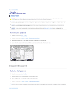
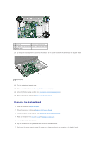
1 screws (9) 2 speakers cable connector 3 AC adapter cable connector 4 display cable grounding screw 5 display cable 15. Lift the system board assembly to disconnect the connector on the system board from the connector on the daughter board. 1 system board 16. Turn the system board assembly over. 17. Follow the instructions from step 3 to step 5 in Removing the Hard Drive. 18. Remove the thermal cooling assembly (see Removing the Thermal Cooling Assembly). 19. Remove the processor module (see Removing the Processor Module). Replacing the System Board 1. Follow the instructions in Before You Begin. 2. Replace the processor module (see Replacing the Processor Module). 3. Replace the thermal cooling assembly (see Replacing the Thermal Cooling Assembly). 4. Follow the instructions from step 4 to step 5 in Replacing the Hard Drive. 5. Turn the system board assembly over. 6. Align the connectors on the system board with the slots on the computer base. 7. Gently press the system board to connect the connector on the system board to the connector on the daughter board.
-
 1
1 -
2
-
3
-
4
-
5
-
6
-
7
-
8
-
9
-
10
-
11
-
12
-
13
-
14
-
15
-
16
-
17
-
18
-
19
-
20
-
21
-
22
-
23
-
24
-
25
-
26
-
27
-
28
-
29
-
30
-
31
-
32
-
33
-
34
-
35
-
36
-
37
-
38
-
39
-
40
-
41
-
42
-
43
-
44
-
45
-
46
-
 47
47 -
 48
48 -
 49
49 -
 50
50 -
 51
51 -
 52
52 -
 53
53
 |
 |
