Dell Inspiron 15 5567 Inspiron 15 5000 Service Manual
Dell Inspiron 15 5567 Manual
 |
View all Dell Inspiron 15 5567 manuals
Add to My Manuals
Save this manual to your list of manuals |
Dell Inspiron 15 5567 manual content summary:
- Dell Inspiron 15 5567 | Inspiron 15 5000 Service Manual - Page 1
Inspiron 15 5000 Service Manual Computer Model: Inspiron 15-5567 Regulatory Model: P66F Regulatory Type: P66F001 - Dell Inspiron 15 5567 | Inspiron 15 5000 Service Manual - Page 2
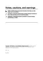
and tells you how to avoid the problem. WARNING: A WARNING indicates a potential for property damage, personal injury, or death. Copyright © 2017 Dell Inc. or its subsidiaries. All rights reserved. Dell, EMC, and other trademarks are trademarks of Dell Inc. or its subsidiaries. Other trademarks may - Dell Inspiron 15 5567 | Inspiron 15 5000 Service Manual - Page 3
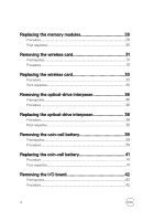
Before working inside your computer 10 Before you begin 10 Safety instructions 10 Recommended tools 11 Screw list 12 After working inside your computer 14 Removing the optical drive 15 Procedure 15 Replacing the optical drive 19 Procedure 19 Removing the base cover 20 Prerequisites 20 - Dell Inspiron 15 5567 | Inspiron 15 5000 Service Manual - Page 4
-requisites 35 Removing the optical-drive interposer 36 Prerequisites 36 Procedure 36 Replacing the optical-drive interposer 38 Procedure 38 Post-requisites 38 Removing the coin-cell battery 39 Prerequisites 39 Procedure 39 Replacing the coin-cell battery 41 Procedure 41 Post-requisites - Dell Inspiron 15 5567 | Inspiron 15 5000 Service Manual - Page 5
44 Procedure 44 Post-requisites 44 Removing the hard drive 45 Prerequisites 45 Procedure 45 Replacing the hard drive 48 Procedure 48 Post-requisites 48 Removing the battery 49 Prerequisites 49 Procedure 49 Replacing the battery 52 Procedure 52 Post-requisites 52 Removing the status - Dell Inspiron 15 5567 | Inspiron 15 5000 Service Manual - Page 6
65 Removing the heat-sink assembly 66 Prerequisites 66 Procedure 67 Replacing the heat-sink assembly 68 Procedure 68 Post-requisites 68 Removing the touch pad 70 Prerequisites 70 Procedure 70 Replacing the touch pad 74 Procedure 74 Post-requisites 75 Removing the display assembly - Dell Inspiron 15 5567 | Inspiron 15 5000 Service Manual - Page 7
80 Post-requisites 80 Removing the display bezel 81 Prerequisites 81 Procedure 81 Replacing the display bezel 83 Procedure 83 Post-requisites 83 Removing the camera 84 Prerequisites 84 Procedure 84 Replacing the camera 86 Procedure 86 Post-requisites 86 Removing the display panel 87 - Dell Inspiron 15 5567 | Inspiron 15 5000 Service Manual - Page 8
and antenna assembly 97 Prerequisites 97 Procedure 97 Replacing the display back-cover and antenna assembly 99 Procedure 99 Post-requisites 99 Removing the power-button module 100 Prerequisites 100 Procedure 100 Replacing the power-button module 102 Procedure 102 Post-requisites 102 - Dell Inspiron 15 5567 | Inspiron 15 5000 Service Manual - Page 9
the power-adapter port 106 Procedure 106 Post-requisites 106 Removing the palm rest and keyboard assembly.........108 Prerequisites 108 Procedure 109 Replacing the palm rest and keyboard assembly......... 110 Procedure 110 Post-requisites 110 Diagnostics 112 Getting help and contacting Dell - Dell Inspiron 15 5567 | Inspiron 15 5000 Service Manual - Page 10
and peripherals, such as keyboard, mouse, and monitor from your computer. 5 Remove any media card and optical disc from your computer, if applicable. 6 Close the display and turn the computer over. GUID-71128823-CE64-4E17-9439-DEE95AF668C4 Safety instructions Use the following safety guidelines - Dell Inspiron 15 5567 | Inspiron 15 5000 Service Manual - Page 11
, and avoid touching pins and contacts. CAUTION: You should only perform troubleshooting and repairs as authorized or directed by the Dell technical assistance team. Damage due to servicing that is not authorized by Dell is not covered by your warranty. See the safety instructions that shipped with - Dell Inspiron 15 5567 | Inspiron 15 5000 Service Manual - Page 12
GUID-816A7381-2933-4438-A177-E6688DBB9E7B Screw list Component Base cover Base cover Base cover Secured to Palm rest and keyboard assembly Palm rest and keyboard assembly Palm rest and keyboard assembly Battery Fan Hard drive Palm rest and keyboard assembly Palm rest and keyboard assembly Hard- - Dell Inspiron 15 5567 | Inspiron 15 5000 Service Manual - Page 13
assembly I/O board Palm rest and keyboard assembly Optical-drive bracket Optical drive Optical-drive interposer Palm rest and keyboard assembly Palm rest and Palm rest and keyboard keyboard assembly bridge assembly Panel Palm rest and keyboard assembly Power-adapter port Palm rest and - Dell Inspiron 15 5567 | Inspiron 15 5000 Service Manual - Page 14
GUID-06588814-2678-4667-9FF9-C009F4BCE185 After working inside your computer CAUTION: Leaving stray or loose screws inside your computer may severely damage your computer. 1 Replace all screws and ensure that no stray screws remain inside your computer. 2 Connect any external devices, peripherals, - Dell Inspiron 15 5567 | Inspiron 15 5000 Service Manual - Page 15
your computer. After working inside your computer, follow the instructions in After working inside your computer. For more safety best practices, see the Regulatory Compliance home page at www.dell.com/ regulatory_compliance. GUID-E85ABD07-B26F-44FC-9731-31D871BC4275 Procedure 1 Remove the screw - Dell Inspiron 15 5567 | Inspiron 15 5000 Service Manual - Page 16
3 Slide the optical-drive assembly out of the optical-drive bay. 1 optical-drive assembly 3 plastic scribe 2 M2x4 screw 4 base cover 4 Remove the screws that secure the optical-drive bracket to the optical drive. 16 - Dell Inspiron 15 5567 | Inspiron 15 5000 Service Manual - Page 17
5 Remove the optical-drive bracket. 1 optical drive 3 optical-drive bracket 2 M2x3 screws (2) 17 - Dell Inspiron 15 5567 | Inspiron 15 5000 Service Manual - Page 18
6 Pull the optical-drive bezel carefully to remove it from the optical drive. 1 optical-drive bezel 3 tabs (3) 2 optical drive 18 - Dell Inspiron 15 5567 | Inspiron 15 5000 Service Manual - Page 19
GUID-01750DAC-3408-4912-B936-7DAA79351AA9 Replacing the optical drive WARNING: Before working inside your computer, read the safety information that shipped with your computer and follow the steps in Before working inside your computer. After working inside your computer, follow the instructions in - Dell Inspiron 15 5567 | Inspiron 15 5000 Service Manual - Page 20
your computer. After working inside your computer, follow the instructions in After working inside your computer. For more safety best practices, see the Regulatory Compliance home page at www.dell.com/ regulatory_compliance. GUID-23D2D516-90B7-4163-A50C-B2E52E691490 Prerequisites Remove the optical - Dell Inspiron 15 5567 | Inspiron 15 5000 Service Manual - Page 21
GUID-B9630B7D-C146-43A6-89CA-DE271F30C997 Procedure 1 Remove the screws that secure the base cover to the palm rest and keyboard assembly. 1 M2.5x8 screws (13) 3 M2x4 screw 2 M2x2 screws (3) 4 base cover 2 Using a plastic scribe, pry the base cover starting from the top-left corner of - Dell Inspiron 15 5567 | Inspiron 15 5000 Service Manual - Page 22
3 Lift the base cover off the palm rest and keyboard assembly at an angle. 1 palm rest and keyboard assembly 3 base cover 2 plastic scribe NOTE: Follow step 4 and 5 only if you want to further remove any component from the computer. 22 - Dell Inspiron 15 5567 | Inspiron 15 5000 Service Manual - Page 23
4 Disconnect the battery cable from the system board. 1 battery cable 2 system board 5 Press and hold the power button for 5 seconds to ground the system board. 23 - Dell Inspiron 15 5567 | Inspiron 15 5000 Service Manual - Page 24
inside your computer, follow the instructions in After working inside your computer. For more safety best practices, see the Regulatory Compliance home page at www.dell.com/ regulatory_compliance. GUID-36436E52-BF74-4CD7-A51E-30CADC145758 Procedure 1 Connect the battery cable to the system board - Dell Inspiron 15 5567 | Inspiron 15 5000 Service Manual - Page 25
assembly, and snap the base cover into place starting from the power-adapter port. 1 base cover 2 power-adapter port 3 Replace the screws that secure the base cover to the palm rest and keyboard assembly. GUID-65FDA1CD-4E26-4BA7-B1DF-FD73E839CF5A Post-requisites Replace the optical drive. 25 - Dell Inspiron 15 5567 | Inspiron 15 5000 Service Manual - Page 26
your computer, follow the instructions in After working inside your computer. For more safety best practices, see the Regulatory Compliance home page at www.dell.com/ regulatory_compliance. GUID-B63E7AE3-1A63-42B8-8121-1A48547C357D Prerequisites 1 Remove the optical drive. 2 Remove the base cover - Dell Inspiron 15 5567 | Inspiron 15 5000 Service Manual - Page 27
2 Remove the memory module from the memory-module slot. 1 securing clips (2) 3 memory-module slot 2 memory module 27 - Dell Inspiron 15 5567 | Inspiron 15 5000 Service Manual - Page 28
your computer. After working inside your computer, follow the instructions in After working inside your computer. For more safety best practices, see the Regulatory Compliance home page at www.dell.com/ regulatory_compliance. GUID-CAB8F52D-7F5B-4847-B34A-91B741249DF9 Procedure 1 Align the notch - Dell Inspiron 15 5567 | Inspiron 15 5000 Service Manual - Page 29
place. NOTE: If you do not hear the click, remove the memory module and reinstall it. 1 notch 3 memory-module slot 2 tab 4 memory module 3 Connect the battery cable to the system board. 29 - Dell Inspiron 15 5567 | Inspiron 15 5000 Service Manual - Page 30
GUID-FC885216-4D9B-490B-8E29-934447E8E5D4 Post-requisites 1 Replace the base cover. 2 Replace the optical drive. 30 - Dell Inspiron 15 5567 | Inspiron 15 5000 Service Manual - Page 31
your computer, follow the instructions in After working inside your computer. For more safety best practices, see the Regulatory Compliance home page at www.dell.com/ regulatory_compliance. GUID-B63E7AE3-1A63-42B8-8121-1A48547C357D Prerequisites 1 Remove the optical drive. 2 Remove the base cover - Dell Inspiron 15 5567 | Inspiron 15 5000 Service Manual - Page 32
3 Slide and remove the wireless card from the wireless-card slot. 1 M2x3 screw 3 antenna cables (2) 5 wireless-card slot 2 wireless-card bracket 4 wireless card 32 - Dell Inspiron 15 5567 | Inspiron 15 5000 Service Manual - Page 33
your computer. After working inside your computer, follow the instructions in After working inside your computer. For more safety best practices, see the Regulatory Compliance home page at www.dell.com/ regulatory_compliance. GUID-89AE71F3-4BEC-4E5E-A9D0-E47D1BEE6532 Procedure CAUTION: To avoid - Dell Inspiron 15 5567 | Inspiron 15 5000 Service Manual - Page 34
6 Replace the screw that secures the wireless-card bracket to the wireless card and the palm rest and keyboard assembly. 1 wireless card 3 wireless-card slot 5 antenna cables (2) 7 wireless-card bracket 2 notch 4 tab 6 M2x3 screw 34 - Dell Inspiron 15 5567 | Inspiron 15 5000 Service Manual - Page 35
GUID-FC885216-4D9B-490B-8E29-934447E8E5D4 Post-requisites 1 Replace the base cover. 2 Replace the optical drive. 35 - Dell Inspiron 15 5567 | Inspiron 15 5000 Service Manual - Page 36
your computer, follow the instructions in After working inside your computer. For more safety best practices, see the Regulatory Compliance home page at www.dell.com/ regulatory_compliance. GUID-B63E7AE3-1A63-42B8-8121-1A48547C357D Prerequisites 1 Remove the optical drive. 2 Remove the base cover - Dell Inspiron 15 5567 | Inspiron 15 5000 Service Manual - Page 37
4 Lift the optical-drive interposer off the palm rest and keyboard assembly. 1 display cable 3 latch 5 M2x2 screws (2) 2 routing guide 4 optical-drive interposer cable 6 optical-drive interposer 37 - Dell Inspiron 15 5567 | Inspiron 15 5000 Service Manual - Page 38
home page at www.dell.com/ regulatory_compliance. GUID-C6F8A5A3-0E1D-447A-B2A2-15472E17B739 Procedure 1 Align the screw holes on the optical-drive interposer with the screw holes on the palm rest and keyboard assembly. 2 Replace the screws that secure the optical-drive interposer to the palm - Dell Inspiron 15 5567 | Inspiron 15 5000 Service Manual - Page 39
1 Remove the optical drive. 2 Remove the base cover. GUID-B5BD7027-9D38-47A1-AE58-B30BEB4BD9C6 Procedure 1 Disconnect the coin-cell battery cable from the system board. 2 Note the coin-cell battery cable routing on the palm rest and keyboard assembly. 3 Remove the coin-cell battery cable from the - Dell Inspiron 15 5567 | Inspiron 15 5000 Service Manual - Page 40
4 Peel off the coin-cell battery from the palm rest and keyboard assembly. 1 system board 3 coin-cell battery cable 5 routing guide 2 palm rest and keyboard assembly 4 coin-cell battery 40 - Dell Inspiron 15 5567 | Inspiron 15 5000 Service Manual - Page 41
and keyboard assembly. 2 Route the coin-cell battery cable through the routing guide on the palm rest and keyboard assembly. 3 Connect the coin-cell battery cable to the system board. GUID-FC885216-4D9B-490B-8E29-934447E8E5D4 Post-requisites 1 Replace the base cover. 2 Replace the optical drive. 41 - Dell Inspiron 15 5567 | Inspiron 15 5000 Service Manual - Page 42
your computer, follow the instructions in After working inside your computer. For more safety best practices, see the Regulatory Compliance home page at www.dell.com/ regulatory_compliance. GUID-B63E7AE3-1A63-42B8-8121-1A48547C357D Prerequisites 1 Remove the optical drive. 2 Remove the base cover - Dell Inspiron 15 5567 | Inspiron 15 5000 Service Manual - Page 43
3 Lift the I/O board off the palm rest and keyboard assembly. 1 latch 3 M2.5x5 screw 5 palm rest and keyboard assembly 2 I/O-board cable 4 I/O board 43 - Dell Inspiron 15 5567 | Inspiron 15 5000 Service Manual - Page 44
. 3 Replace the screw that secures the I/O board to the palm rest and keyboard assembly. 4 Connect the I/O board-cable to the system board and close the latch to secure the cable. GUID-FC885216-4D9B-490B-8E29-934447E8E5D4 Post-requisites 1 Replace the base cover. 2 Replace the optical drive. 44 - Dell Inspiron 15 5567 | Inspiron 15 5000 Service Manual - Page 45
instructions in After working inside your computer. For more safety best practices, see the Regulatory Compliance home page at www.dell.com/ regulatory_compliance. CAUTION: Hard drives are fragile. Exercise care when handling the hard drive. CAUTION: To avoid data loss, do not remove the hard drive - Dell Inspiron 15 5567 | Inspiron 15 5000 Service Manual - Page 46
3 Lift the hard-drive assembly along with its cable off the palm rest and keyboard assembly. 1 pull tab 3 hard-drive cable 5 hard-drive assembly 2 latch 4 M2.5x5 screws (3) 6 palm rest and keyboard assembly 46 - Dell Inspiron 15 5567 | Inspiron 15 5000 Service Manual - Page 47
4 Disconnect the interposer from the hard-drive assembly. 1 hard-drive assembly 2 interposer 5 Remove the screws that secure the hard-drive bracket to the hard drive. 6 Lift the hard drive off the hard-drive bracket. 1 M3x3 screws (4) 3 hard drive 2 hard-drive bracket 47 - Dell Inspiron 15 5567 | Inspiron 15 5000 Service Manual - Page 48
screw holes on the palm rest and keyboard assembly. 5 Replace the screws that secure the hard-drive assembly to the palm rest and keyboard assembly. 6 Connect the hard-drive cable to the system board and close the latch to secure the cable. GUID-E79B37C0-5C80-4495-B8C4-665DB1C34C22 Post-requisites - Dell Inspiron 15 5567 | Inspiron 15 5000 Service Manual - Page 49
-8345-DAB052C258F8 Prerequisites 1 Remove the optical drive. 2 Remove the base cover. 3 Remove the I/O board. 4 Remove the hard drive. GUID-21C6DBA6-B731-4F93-ADFB-F07DEDBF9DC9 Procedure 1 Remove the screws that secure the battery bracket to the system board and palm rest and keyboard assembly. 49 - Dell Inspiron 15 5567 | Inspiron 15 5000 Service Manual - Page 50
Lift and remove the battery bracket. 1 system board 3 battery bracket 5 palm rest and keyboard assembly 2 M2.5x5 screws (2) 4 battery 3 Remove the screw that secures the battery to the palm rest and keyboard assembly. NOTE: Note the location of the screw that secures the battery to the palm rest - Dell Inspiron 15 5567 | Inspiron 15 5000 Service Manual - Page 51
4 Lift the battery off the palm rest and keyboard assembly. 1 M2.5x5 screw 3 palm rest and keyboard assembly 2 battery 51 - Dell Inspiron 15 5567 | Inspiron 15 5000 Service Manual - Page 52
and keyboard assembly. 4 Replace the screws that secure the battery bracket to the system board and palm rest and keyboard assembly. GUID-ADB6AB7C-464F-4F3F-AD1C-B142692E04D4 Post-requisites 1 Replace the hard drive. 2 Replace the I/O board. 3 Replace the base cover. 4 Replace the optical drive. 52 - Dell Inspiron 15 5567 | Inspiron 15 5000 Service Manual - Page 53
the I/O board. 4 Remove the hard drive. 5 Remove the battery. GUID-FFF45532-0BFE-49E4-A031-AEF28CE0D877 Procedure 1 Open the latch and disconnect the status-light board cable from the system board. 2 Peel off the status-light board cable from the palm rest and keyboard assembly. 3 Push the tab that - Dell Inspiron 15 5567 | Inspiron 15 5000 Service Manual - Page 54
4 Lift the status-light board along with its cable off the palm rest and keyboard assembly. 1 system board 3 palm rest and keyboard assembly 5 tab 7 status-light board cable 2 latch 4 touch-pad bracket 6 status-light board 54 - Dell Inspiron 15 5567 | Inspiron 15 5000 Service Manual - Page 55
palm rest and keyboard assembly. 4 Slide the status-light board cable into the connector on the system board and close the latch to secure the cable. GUID-1F9A097D-6ED1-4162-8C96-329D29AC0D98 Post-requisites 1 Replace the battery. 2 Replace the hard drive. 3 Replace the I/O board. 4 Replace the base - Dell Inspiron 15 5567 | Inspiron 15 5000 Service Manual - Page 56
Compliance home page at www.dell.com/ regulatory_compliance. GUID-771C8E2E-8A6F-4EFC-8131-26653D7702F5 Prerequisites 1 Remove the optical drive. 2 Remove the base cover. 3 Remove the I/O board. 4 Remove the hard drive. 5 Remove the battery. GUID-FE7C574B-2841-4499-BF3A-0C6B0F7AF780 Procedure - Dell Inspiron 15 5567 | Inspiron 15 5000 Service Manual - Page 57
4 Lift the speakers along with its cable off the palm rest and keyboard assembly. 1 system board 3 speakers (2) 5 routing guides 2 speaker cable 4 palm rest and keyboard assembly 57 - Dell Inspiron 15 5567 | Inspiron 15 5000 Service Manual - Page 58
the status-light board cable into the connector on the system board and close the latch to secure the cable. GUID-1F9A097D-6ED1-4162-8C96-329D29AC0D98 Post-requisites 1 Replace the battery. 2 Replace the hard drive. 3 Replace the I/O board. 4 Replace the base cover. 5 Replace the optical drive. 58 - Dell Inspiron 15 5567 | Inspiron 15 5000 Service Manual - Page 59
you can reconnect the cables correctly after you replace the system board. GUID-C052C317-4BC4-481A-95A3-82980917C6F5 Prerequisites 1 Remove the optical drive. 2 Remove the base cover. 3 Remove the I/O board. 4 Remove the hard drive. 5 Remove the battery. 6 Remove the memory modules. 7 Remove the - Dell Inspiron 15 5567 | Inspiron 15 5000 Service Manual - Page 60
hinge to the palm rest and keyboard assembly. 2 Open the right display hinge. 1 M2.5x5 screws (2) 3 system board 2 right display hinge 3 Open the latch and disconnect the display cable from the system board. 4 Lift the latch and pull the optical-drive interposer cable from the system board - Dell Inspiron 15 5567 | Inspiron 15 5000 Service Manual - Page 61
the speaker cable and coin-cell battery cable from the system board. 1 optical-drive interposer cable 3 status-light board cable 5 coin-cell battery cable 7 touch-pad cable 9 display cable 2 latches (4) 4 speaker cable 6 keyboard cable 8 keyboard backlight cable 8 Remove the screws that - Dell Inspiron 15 5567 | Inspiron 15 5000 Service Manual - Page 62
10 Carefully turn the system-board assembly over. 1 M2.5x5 screw 3 M2.5x5 screw 2 system board 11 Lift the latch and pull the power-adapter port cable from the system board. 12 Disconnect the power-button cable from the system board. 62 - Dell Inspiron 15 5567 | Inspiron 15 5000 Service Manual - Page 63
13 Peel off the power-adapter port cable from the back of the heat-sink assembly. 1 power-button cable 3 system board 14 Remove the heat-sink assembly. 2 power-adapter port cable 4 latch 63 - Dell Inspiron 15 5567 | Inspiron 15 5000 Service Manual - Page 64
BIOS setup program. You must make the appropriate changes again after you replace the system board. GUID-0F6C8740-9AC5-4E04-87E5-9BD430222F1B Procedure 1 Replace the heat-sink assembly. 2 Connect the power-adapter port cable and power-button board cable to the back of the system board. 3 Carefully - Dell Inspiron 15 5567 | Inspiron 15 5000 Service Manual - Page 65
. 15 Replace the screws that secure the right display hinge to the palm rest and keyboard assembly. GUID-F95B5498-F2B9-416B-95E4-296FC791E7D1 Post-requisites 1 Replace the wireless card. 2 Replace the memory modules. 3 Replace the battery. 4 Replace the hard drive. 5 Replace the I/O board. 6 Replace - Dell Inspiron 15 5567 | Inspiron 15 5000 Service Manual - Page 66
can reduce the heat transfer capability of the thermal grease. GUID-BA85A58B-5006-4CEE-BACF-CE1B91EE0CE0 Prerequisites 1 Remove the optical drive. 2 Remove the base cover. 3 Remove the I/O board. 4 Remove the hard drive. 5 Remove the battery. 6 Remove the memory modules. 7 Remove the wireless card - Dell Inspiron 15 5567 | Inspiron 15 5000 Service Manual - Page 67
GUID-120C147E-74A5-4381-A3D9-385D7BD8FAB4 Procedure CAUTION: Place the system board on a clean and flat surface. 1 Disconnect the fan cable from the system board. 2 In sequential order (as indicated on the heat-sink assembly), loosen the captive screws that secure the heat-sink assembly - Dell Inspiron 15 5567 | Inspiron 15 5000 Service Manual - Page 68
grease can be reused if the original system board and fan are reinstalled together. If either the system board or the fan is replaced, use the thermal pad provided in the kit to ensure that thermal conductivity is achieved. GUID-E36290DD-4C1A-4CCD-8DA7-7E8C384BAB63 Procedure 1 Place the heat-sink - Dell Inspiron 15 5567 | Inspiron 15 5000 Service Manual - Page 69
4 Replace the battery. 5 Replace the hard drive. 6 Replace the I/O board. 7 Replace the base cover. 8 Replace the optical drive. 69 - Dell Inspiron 15 5567 | Inspiron 15 5000 Service Manual - Page 70
the Regulatory Compliance home page at www.dell.com/ regulatory_compliance. GUID-5A58D3F3-36FE-4C9A-9C6A-8BAE136335F3 Prerequisites 1 Remove the optical drive. 2 Remove the base cover. 3 Remove the I/O board. 4 Remove the hard drive. 5 Remove the battery. 6 Follow the procedure from step 1 to step - Dell Inspiron 15 5567 | Inspiron 15 5000 Service Manual - Page 71
3 Peel off the tape that secures the touch pad to the palm rest and keyboard assembly. 1 touch-pad cable 3 tape 5 keyboard backlight cable 2 latch 4 touch pad 6 palm rest and keyboard assembly 4 Remove the screws that secure the touch-pad bracket to the palm rest and keyboard assembly. 71 - Dell Inspiron 15 5567 | Inspiron 15 5000 Service Manual - Page 72
5 Lift the touch-pad bracket off the palm rest and keyboard assembly. 1 M2x2 screws (3) 3 touch pad 2 touch-pad bracket 4 palm rest and keyboard assembly 6 Remove the screws that secure the touch pad to the palm rest and keyboard assembly. 72 - Dell Inspiron 15 5567 | Inspiron 15 5000 Service Manual - Page 73
7 Lift the touch pad off the palm rest and keyboard assembly. 1 M2x2 screws (4) 3 touch pad 2 palm rest and keyboard assembly 73 - Dell Inspiron 15 5567 | Inspiron 15 5000 Service Manual - Page 74
NOTE: Ensure that the touch pad is aligned with the guides available on the palm-rest and keyboard assembly, and the gap on either sides of the touch pad is equal. 1 Align the screw holes on the touch pad with the screw holes on the palm rest and keyboard assembly. 2 Replace the screws that secure - Dell Inspiron 15 5567 | Inspiron 15 5000 Service Manual - Page 75
heat-sink assembly. 2 Replace the system-board assembly. 3 Replace the wireless card. 4 Replace the memory modules. 5 Follow the procedure from step 3 to step 4 in "Replacing the status-light board". 6 Replace the battery. 7 Replace the hard drive. 8 Replace the I/O board. 9 Replace the base cover - Dell Inspiron 15 5567 | Inspiron 15 5000 Service Manual - Page 76
the Regulatory Compliance home page at www.dell.com/ regulatory_compliance. GUID-0F207900-F445-4346-95E3-8E67C1381357 Prerequisites 1 Remove the optical drive. 2 Remove the base cover. GUID-C6B13D9B-C7C6-457A-A993-03E1DAE7374C Procedure 1 Remove the battery cable from the system board. 2 Note the - Dell Inspiron 15 5567 | Inspiron 15 5000 Service Manual - Page 77
3 Lift the latch and disconnect the display cable from the system board. 1 display cable 3 latch 2 system board 4 routing guides 4 Remove the screws that secure the display hinges to the palm rest and keyboard assembly. 77 - Dell Inspiron 15 5567 | Inspiron 15 5000 Service Manual - Page 78
5 Open the display hinges. 1 M2.5x5 screws (4) 3 display assembly 2 display hinges (2) 4 palm rest and keyboard assembly 78 - Dell Inspiron 15 5567 | Inspiron 15 5000 Service Manual - Page 79
6 Lift the palm rest and keyboard assembly off the display assembly. 1 display hinges (2) 3 display assembly 2 palm rest and keyboard assembly 79 - Dell Inspiron 15 5567 | Inspiron 15 5000 Service Manual - Page 80
and keyboard. 5 Slide the display cable to the connector on the system board and close the latch to secure the cable. 6 Slide the battery cable to the connector on the system board. GUID-75473F2A-D495-4825-AB73-8FF1F86AA67A Post-requisites 1 Replace the base cover. 2 Replace the optical drive. 80 - Dell Inspiron 15 5567 | Inspiron 15 5000 Service Manual - Page 81
your computer, follow the instructions in After working inside your computer. For more safety best practices, see the Regulatory Compliance home page at www.dell.com/ regulatory_compliance. GUID-14BF4286-840E-48B0-9B26-0ADACD550E41 Prerequisites 1 Remove the optical drive. 2 Remove the base cover - Dell Inspiron 15 5567 | Inspiron 15 5000 Service Manual - Page 82
2 Remove the display bezel off the display back-cover. 1 display back-cover 3 plastic scribe 2 display bezel 82 - Dell Inspiron 15 5567 | Inspiron 15 5000 Service Manual - Page 83
your computer. After working inside your computer, follow the instructions in After working inside your computer. For more safety best practices, see the Regulatory Compliance home page at www.dell.com/ regulatory_compliance. GUID-78F0CB5B-546B-4F5B-9CF4-7B7A55F91993 Procedure Align the display - Dell Inspiron 15 5567 | Inspiron 15 5000 Service Manual - Page 84
your computer, follow the instructions in After working inside your computer. For more safety best practices, see the Regulatory Compliance home page at www.dell.com/ regulatory_compliance. GUID-47BF2DFA-16A7-4EA9-A410-F1CFFE4F1A77 Prerequisites 1 Remove the optical drive. 2 Remove the base cover - Dell Inspiron 15 5567 | Inspiron 15 5000 Service Manual - Page 85
3 Disconnect the camera cable from the camera module. 1 plastic scribe 3 camera cable 2 camera module 4 display assembly 85 - Dell Inspiron 15 5567 | Inspiron 15 5000 Service Manual - Page 86
your computer. After working inside your computer, follow the instructions in After working inside your computer. For more safety best practices, see the Regulatory Compliance home page at www.dell.com/ regulatory_compliance. GUID-596BE7A1-7CE5-48F7-A59B-6BD7471079D1 Procedure 1 Connect the camera - Dell Inspiron 15 5567 | Inspiron 15 5000 Service Manual - Page 87
your computer, follow the instructions in After working inside your computer. For more safety best practices, see the Regulatory Compliance home page at www.dell.com/ regulatory_compliance. GUID-47BF2DFA-16A7-4EA9-A410-F1CFFE4F1A77 Prerequisites 1 Remove the optical drive. 2 Remove the base cover - Dell Inspiron 15 5567 | Inspiron 15 5000 Service Manual - Page 88
2 Lift the display panel gently and turn it over. 1 M2x3 screws (4) 3 display back-cover 2 display panel 3 Peel the tape adhering the display cable to the back of the display panel. 4 Lift the latch and disconnect the display cable from the display-panel cable connector. 88 - Dell Inspiron 15 5567 | Inspiron 15 5000 Service Manual - Page 89
5 Lift the display panel away from the display back-cover. 1 display panel 3 display cable 5 latch 2 tape 4 display back-cover 89 - Dell Inspiron 15 5567 | Inspiron 15 5000 Service Manual - Page 90
the screw holes on the display back-cover. 5 Replace the screws that secure the display panel to the display back-cover. GUID-840C2C06-04A1-4A7C-9E4C-FA04049E9AC6 Post-requisites 1 Replace the display bezel. 2 Replace the display assembly. 3 Replace the base cover. 4 Replace the optical drive. 90 - Dell Inspiron 15 5567 | Inspiron 15 5000 Service Manual - Page 91
your computer, follow the instructions in After working inside your computer. For more safety best practices, see the Regulatory Compliance home page at www.dell.com/ regulatory_compliance. GUID-63303845-D3AB-4329-B635-9CFB29C0A8DD Prerequisites 1 Remove the optical drive. 2 Remove the base cover - Dell Inspiron 15 5567 | Inspiron 15 5000 Service Manual - Page 92
3 Lift the display-hinge brackets off the display back-cover. 1 M2x3 screws (2) 3 display hinges (2) 5 display back-cover 2 display-hinge brackets (2) 4 M2.5x3 screws (6) 92 - Dell Inspiron 15 5567 | Inspiron 15 5000 Service Manual - Page 93
back-cover. 3 Replace the screws that secure the display hinges to the display back-cover. GUID-795CDDC3-FB76-4676-BA97-5DF9F6B58E8E Post-requisites 1 Replace the display panel. 2 Replace the display bezel. 3 Replace the display assembly. 4 Replace the base cover. 5 Replace the optical drive. 93 - Dell Inspiron 15 5567 | Inspiron 15 5000 Service Manual - Page 94
your computer, follow the instructions in After working inside your computer. For more safety best practices, see the Regulatory Compliance home page at www.dell.com/ regulatory_compliance. GUID-68120619-E91E-4F8C-986E-59BCDC54CE35 Prerequisites 1 Remove the optical drive. 2 Remove the base cover - Dell Inspiron 15 5567 | Inspiron 15 5000 Service Manual - Page 95
4 Note the display cable routing and remove the display cable from the display back-cover. 1 display back-cover 3 tapes (2) 5 camera cable 2 display cable 4 camera module 95 - Dell Inspiron 15 5567 | Inspiron 15 5000 Service Manual - Page 96
into the connector on the camera module to secure the cable. GUID-9AFFD6E5-D11E-45DB-9FBC-58C05D3B6A67 Post-requisites 1 Replace the display hinges. 2 Replace the display panel. 3 Replace the display bezel. 4 Replace the display assembly. 5 Replace the base cover. 6 Replace the optical drive. 96 - Dell Inspiron 15 5567 | Inspiron 15 5000 Service Manual - Page 97
your computer, follow the instructions in After working inside your computer. For more safety best practices, see the Regulatory Compliance home page at www.dell.com/ regulatory_compliance. GUID-72DBDF52-9EEB-41F8-934F-C36FB6862459 Prerequisites 1 Remove the optical drive. 2 Remove the base cover - Dell Inspiron 15 5567 | Inspiron 15 5000 Service Manual - Page 98
1 display back-cover and antenna assembly 98 - Dell Inspiron 15 5567 | Inspiron 15 5000 Service Manual - Page 99
flat surface. GUID-3EAC82E6-1587-42F8-A55F-CC67B26D1173 Post-requisites 1 Replace the camera. 2 Replace the display cable. 3 Replace the display hinges. 4 Replace the display panel. 5 Replace the display bezel. 6 Replace the display assembly. 7 Replace the base cover. 8 Replace the optical drive. 99 - Dell Inspiron 15 5567 | Inspiron 15 5000 Service Manual - Page 100
the Regulatory Compliance home page at www.dell.com/ regulatory_compliance. GUID-2014AA68-97FB-4DEC-869F-F10535285070 Prerequisites 1 Remove the optical drive. 2 Remove the base cover. 3 Remove the I/O board. 4 Remove the hard drive. 5 Remove the battery. 6 Remove the memory modules. 7 Remove the - Dell Inspiron 15 5567 | Inspiron 15 5000 Service Manual - Page 101
3 Remove the power-button board cable from the routing guides. 4 Lift the power-button board at an angle along with the cable off the palm rest and keyboard assembly. 1 tape 3 power-button board 5 power-button board cable 2 M2x2 Big Head screw 4 palm rest and keyboard assembly 101 - Dell Inspiron 15 5567 | Inspiron 15 5000 Service Manual - Page 102
rest and keyboard assembly. GUID-354835A2-18DD-4B65-AFD4-8D21647BC5EE Post-requisites 1 Replace the display panel. 2 Replace the heat-sink assembly. 3 Replace the system-board assembly. 4 Replace the wireless card. 5 Replace the memory modules. 6 Replace the battery. 7 Replace the hard drive. 102 - Dell Inspiron 15 5567 | Inspiron 15 5000 Service Manual - Page 103
8 Replace the I/O board. 9 Replace the base cover. 10 Replace the optical drive. 103 - Dell Inspiron 15 5567 | Inspiron 15 5000 Service Manual - Page 104
the Regulatory Compliance home page at www.dell.com/ regulatory_compliance. GUID-533C8EEA-9B98-43B9-907E-6DC1C1B75269 Prerequisites 1 Remove the optical drive. 2 Remove the base cover. 3 Remove the I/O board. 4 Remove the hard drive. 5 Remove the battery. 6 Remove the status-light board. 7 Remove - Dell Inspiron 15 5567 | Inspiron 15 5000 Service Manual - Page 105
Remove the power-adapter port cable from the routing guides on the palm rest and keyboard assembly. 3 Lift the power-adapter port along with its cable off the palm rest and keyboard assembly. 1 power-adapter port 3 routing guides 5 palm rest and keyboard assembly 2 M2x3 screw 4 power-adapter port - Dell Inspiron 15 5567 | Inspiron 15 5000 Service Manual - Page 106
at www.dell.com/ regulatory_compliance. GUID-FD52A5F5-3882-449A-BD56-FC7757F972EE Procedure 1 Place the power-adapter port into the slot on the palm rest and keyboard assembly. 2 Align the screw hole on the power-adapter port with the screw hole on the palm rest and keyboard assembly. 3 Replace the - Dell Inspiron 15 5567 | Inspiron 15 5000 Service Manual - Page 107
7 Replace the battery. 8 Replace the hard drive. 9 Replace the I/O board. 10 Replace the base cover. 11 Replace the optical drive. 107 - Dell Inspiron 15 5567 | Inspiron 15 5000 Service Manual - Page 108
the Regulatory Compliance home page at www.dell.com/ regulatory_compliance. GUID-BA78C85A-366D-40ED-917A-3249EA4C4E25 Prerequisites 1 Remove the optical drive. 2 Remove the base cover. 3 Remove the I/O board. 4 Remove the hard drive. 5 Remove the battery. 6 Remove the status-light board. 7 Remove - Dell Inspiron 15 5567 | Inspiron 15 5000 Service Manual - Page 109
GUID-028698CB-A438-4E7B-8EA1-362AC3DE6AE8 Procedure After performing the steps in prerequisites, we are left with the palmrest. 1 palmrest 109 - Dell Inspiron 15 5567 | Inspiron 15 5000 Service Manual - Page 110
1 Replace the power-adapter port. 2 Replace the power-button module. 3 Replace the display back-cover and antenna assembly. 4 Replace the speakers. 5 Replace the touch pad. 6 Replace the heat-sink assembly. 7 Replace the system-board assembly. 8 Replace the coin-cell battery. 9 Replace the - Dell Inspiron 15 5567 | Inspiron 15 5000 Service Manual - Page 111
13 Replace the hard drive. 14 Replace the I/O board. 15 Replace the base cover. 16 Replace the optical drive. 111 - Dell Inspiron 15 5567 | Inspiron 15 5000 Service Manual - Page 112
GUID-607BF083-192E-460A-A921-DAF92E1E5297 Diagnostics Power and battery-status light/hard-drive activity light Indicates the battery-charge status or the hard-drive activity. NOTE: Press Fn+H to toggle this light between power and battery-status light and hard-drive activity light. Hard-drive - Dell Inspiron 15 5567 | Inspiron 15 5000 Service Manual - Page 113
Light pattern 2,3 2,4 2,5 2,6 2,7 3,1 3,2 3,3 3,4 Problem description No memory or RAM detected Memory or RAM failure Invalid memory installed System board or chipset error LCD failure CMOS battery failure PCI or video card or chip failure Recovery image not found Recovery image found but invalid - Dell Inspiron 15 5567 | Inspiron 15 5000 Service Manual - Page 114
and services Dell Help & Support app www.dell.com Get started app Accessing help In Windows search, type Help and Support, and press Enter. Online help for operating system www.dell.com/support/windows www.dell.com/support/linux Troubleshooting information, user manuals, setup instructions - Dell Inspiron 15 5567 | Inspiron 15 5000 Service Manual - Page 115
NOTE: Availability varies by country and product, and some services may not be available in your country. NOTE: If you do not have an active internet connection, you can find contact information on your purchase invoice, packing slip, bill, or Dell product catalog. 115
-
 1
1 -
 2
2 -
 3
3 -
 4
4 -
 5
5 -
 6
6 -
 7
7 -
8
-
9
-
10
-
11
-
12
-
13
-
14
-
15
-
16
-
17
-
18
-
19
-
20
-
21
-
22
-
23
-
24
-
25
-
26
-
27
-
28
-
29
-
30
-
31
-
32
-
33
-
34
-
35
-
36
-
37
-
38
-
39
-
40
-
41
-
42
-
43
-
44
-
45
-
46
-
47
-
48
-
49
-
50
-
51
-
52
-
53
-
54
-
55
-
56
-
57
-
58
-
59
-
60
-
61
-
62
-
63
-
64
-
65
-
66
-
67
-
68
-
69
-
70
-
71
-
72
-
73
-
74
-
75
-
76
-
77
-
78
-
79
-
80
-
81
-
82
-
83
-
84
-
85
-
86
-
87
-
88
-
89
-
90
-
91
-
92
-
93
-
94
-
95
-
96
-
97
-
98
-
99
-
100
-
101
-
102
-
103
-
104
-
105
-
106
-
107
-
108
-
109
-
110
-
111
-
112
-
113
-
114
-
115
 |
 |

Inspiron 15 5000
Service Manual
Computer Model: Inspiron 15-5567
Regulatory Model: P66F
Regulatory Type: P66F001