Dell Inspiron 1525 Service Manual - Page 19
Display Bezel - wireless antenna
 |
View all Dell Inspiron 1525 manuals
Add to My Manuals
Save this manual to your list of manuals |
Page 19 highlights
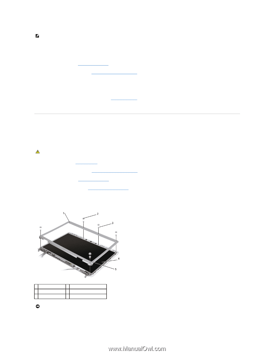
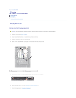
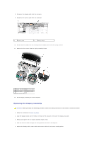
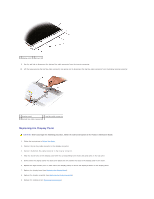
NOTE: Ensure that the display cable, camera cable, and antenna cables are properly routed and secured beneath the plastic tabs. 6. Connect the display cable to the display cable connector on the system board. 7. Connect the camera cables to the camera cable connector on the system board. 8. Replace the keyboard (see Replacing the Keyboard). 9. Replace the center control cover (see Replacing the Center Control Cover). 10. Close the display and turn the computer over. 11. Replace and tighten the two screws securing the display assembly from the bottom of the computer. 12. Connect the antennae cables to the Mini-Cards (see Wireless Mini- Cards). 13. Replace the back cover and tighten the eight captive screws on the cover. Display Bezel Removing the Display Bezel CAUTION: Before you begin the following procedure, follow the safety instructions in the Product Information Guide. 1. Follow the instructions in Before You Begin. 2. Remove the center control cover (see Removing the Center Control Cover). 3. Remove the keyboard (see Removing the Keyboard). 4. Remove the display assembly (see Removing the Display Assembly). 5. Remove the six rubber display bumpers from around the display bezel. 6. Remove the captive screw and five shoulder screws from around the display bezel. 1 captive screw 2 rubber display bumpers (6) 3 shoulder screws (5) 4 display panel 5 display bezel NOTICE: Removal of the bezel from the display back cover requires extreme care to avoid damage to the bezel and the display panel. 7. Starting from the bottom corner of the display panel, use your fingers to pry the bezel from the top cover, then lift the inside edges to separate the
-
 1
1 -
2
-
3
-
4
-
5
-
6
-
7
-
8
-
9
-
10
-
11
-
12
-
13
-
 14
14 -
 15
15 -
 16
16 -
 17
17 -
 18
18 -
 19
19 -
 20
20 -
 21
21 -
 22
22 -
 23
23 -
 24
24 -
25
-
26
-
27
-
28
-
29
-
30
-
31
-
32
-
33
-
34
-
35
-
36
-
37
-
38
-
39
-
40
-
41
-
42
-
43
-
44
-
45
-
46
-
47
-
48
-
49
-
50
-
51
 |
 |