Dell Inspiron 545 Service Manual
Dell Inspiron 545 Manual
 |
View all Dell Inspiron 545 manuals
Add to My Manuals
Save this manual to your list of manuals |
Dell Inspiron 545 manual content summary:
- Dell Inspiron 545 | Service Manual - Page 1
Dell™ Inspiron™ 535/537/545/546 Service Manual Technical Overview Before You Begin Computer Cover Front Bezel Memory PCI and PCI Express Cards Drives Models DCME and DCMF Fans Front I/O Panel Processor System Board Power Supply Battery System Setup Notes, Cautions, and Warnings NOTE: A NOTE - Dell Inspiron 545 | Service Manual - Page 2
Back to Contents Page Before You Begin Dell™ Inspiron™ 535/537/545/546 Service Manual Technical Specifications Recommended Tools Turning Off Your Computer Safety Instructions This chapter provides procedures for removing and installing the components in your computer. Unless otherwise noted, each - Dell Inspiron 545 | Service Manual - Page 3
4. Disconnect your computer and all attached devices from their electrical outlets. 5. Press and hold the power button while the system is unplugged to ground the system board. CAUTION: Before touching anything inside your computer, ground yourself by touching an unpainted metal surface, such as the - Dell Inspiron 545 | Service Manual - Page 4
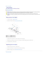
Back to Contents Page Front Bezel Dell™ Inspiron™ 535/537/545/546 Service Manual Removing the Front Bezel Replacing the Front Bezel WARNING: Before working inside your computer, read the safety information that shipped with your computer. For additional safety best practices information, see - Dell Inspiron 545 | Service Manual - Page 5
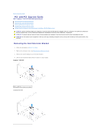
Back to Contents Page PCI and PCI Express Cards Dell™ Inspiron™ 535/537/545/546 Service Manual Removing the Card Retention Bracket Replacing the Card Retention Bracket Removing PCI and PCI Express Cards Replacing PCI and PCI Express Cards Configuring Your Computer After Removing or Installing a PCI/ - Dell Inspiron 545 | Service Manual - Page 6
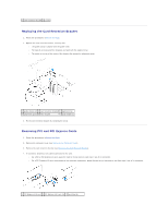
bar. l The notch in the top of the card or filler bracket fits around the alignment guide. 1 guide clamps (2) 2 card retention bracket 3 alignment bar 4 alignment guide 5 filler bracket 6 guide notch (2) 3. Fix the card retention bracket by replacing the screw. Removing PCI and PCI Express - Dell Inspiron 545 | Service Manual - Page 7
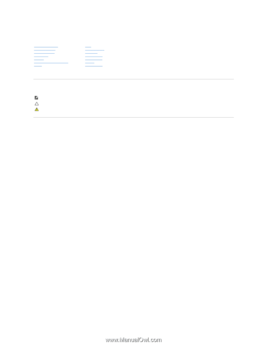
outlets, and then turn them on. 8. Remove the card's driver from the operating system. 9. To complete the removal procedure, see Configuring Your Computer After Removing or Installing a PCI/PCI Express Card. Replacing PCI and PCI Express Cards 1. Follow the procedures in Before You Begin. 2. Remove - Dell Inspiron 545 | Service Manual - Page 8
on location of external connectors, see the Setup Guide. For information on installing drivers and software for your card, see the documentation that shipped with the card. Sound Card Installed Removed 1. Enter system setup (see Entering System Setup) 2. Go to Onboard Audio Controller and then - Dell Inspiron 545 | Service Manual - Page 9
Back to Contents Page Battery Dell™ Inspiron™ 535/537/545/546 Service Manual Removing the Battery Replacing the Battery WARNING: Before Battery 1. Record all the screens in system setup (see System Setup) so that you can restore the correct settings after the new battery has been installed. 2. Follow - Dell Inspiron 545 | Service Manual - Page 10
Back to Contents Page - Dell Inspiron 545 | Service Manual - Page 11
to Contents Page Computer Cover Dell™ Inspiron™ 535/537/545/546 Service Manual Removing the Computer Cover Replacing the Computer Cover WARNING: -panel inserts, etc.) removed. CAUTION: Ensure that sufficient space exists to support the system with the cover removed-at least 30 cm (1 ft.) of desk top - Dell Inspiron 545 | Service Manual - Page 12
1 screws (2) 2 computer cover 3 front of the computer 4 slot 7. Place the computer in an upright position. CAUTION: Ensure that none of the system air-vents are blocked. Blocking them would cause serious thermal problems. Back to Contents Page - Dell Inspiron 545 | Service Manual - Page 13
to Contents Page Processor Dell™ Inspiron™ 535/537/545/546 Service Manual Removing the Processor Replacing the Processor WARNING: the Processor Fan and Heat Sink Assembly). NOTE: Unless a new heat sink is required for the new processor, reuse the original heat sink assembly when you replace the - Dell Inspiron 545 | Service Manual - Page 14
the release position so that the socket is ready for the new processor. Replacing the Processor CAUTION: Ground yourself by touching an unpainted metal surface on the back , move it to that position. Inspiron 535/537/545 1 front alignment notch 2 processor pin-1 indicator 3 rear alignment notch - Dell Inspiron 545 | Service Manual - Page 15
3 processor 4 release lever 4. For Inspiron 535/537/545, orient the front and rear alignment-notches new thermal grease to the top of the processor. 11. Replace the processor fan/heat sink assembly (see Replacing the Processor Fan and Heat Sink Assembly). CAUTION: Ensure that the processor fan - Dell Inspiron 545 | Service Manual - Page 16
Back to Contents Page Drives Dell™ Inspiron™ 535/537/545/546 Service Manual Removing a Hard Drive Replacing a Hard Drive Removing a Media Card Reader Replacing a Media Card Reader Removing an Optical Drive Replacing an Optical Drive WARNING: Before working inside your computer, read the safety - Dell Inspiron 545 | Service Manual - Page 17
configured for your computer. 4. Slide the hard drive into the hard drive bay. 5. Align and replace the four screws that secure the hard drive to the hard drive bay. 6. Connect the power and data cables to the hard drive. 7. Connect the data cable to the system board connector. 8. Check all cables - Dell Inspiron 545 | Service Manual - Page 18
before the FlexBay USB cable is connected. 8. Connect the FlexBay USB cable and power cable to the back of the media card reader. 9. Connect the FlexBay USB cable to the internal USB connector on the system board (see System Board Components). 10. Replace the bezel (see Replacing the Front Bezel - Dell Inspiron 545 | Service Manual - Page 19
(see Replacing the Computer Cover). 10. Connect your computer and devices to their electrical outlets, and turn them on. See the documentation that came with the drive for instructions on installing any software required for drive operation. 11. Check the System Setup for drive configuration changes - Dell Inspiron 545 | Service Manual - Page 20
Fans Dell™ Inspiron™ 535/537/545/546 Service Manual Removing the Processor Fan and Heat Sink Assembly Replacing the Processor Fan and Heat Sink Assembly Removing the Chassis Fan Replacing the Chassis Fan fan and heat sink assembly cable from the processor fan connector on the system board (see System - Dell Inspiron 545 | Service Manual - Page 21
operation. 2. Apply the new thermal grease to the top of the processor. 3. Replace the processor fan and heat sink assembly. Inspiron 535/537/545 a. Align the captive screws on the processor fan and heat sink assembly to the four metal screw hole projections on the system board. b. Tighten the - Dell Inspiron 545 | Service Manual - Page 22
Disconnect the chassis fan cable from the chassis fan connector on the system board (see System Board Components). 4. Remove the screws securing the chassis fan. 5. Slide the chassis fan towards the front of the computer and lift it up. Inspiron™ 535/537 1 screws (2) 2 chassis fan Inspiron 545/546 - Dell Inspiron 545 | Service Manual - Page 23
place towards the back of the computer. 3. Replace the screws that secure the chassis fan. 4. Connect the chassis fan cable to the chassis fan connector on the system board (see System Board Components). 5. Replace the computer cover (see Replacing the Computer Cover). 6. Connect your computer and - Dell Inspiron 545 | Service Manual - Page 24
Dell™ Inspiron™ 535/537/545/546 Service Manual Removing the Front I/O Panel Replacing that you can re-route them correctly when installing the new front I/O panel. 1. Follow the procedures in Before that are connected to the I/O panel from the system board connectors. 5. Remove the screw that secures - Dell Inspiron 545 | Service Manual - Page 25
5. Replace the computer cover (see Replacing the Computer Cover). 6. Connect your computer and devices to an electrical outlet, and turn them on. Back to Contents Page - Dell Inspiron 545 | Service Manual - Page 26
Back to Contents Page Memory Dell™ Inspiron™ 535/537/545/546 Service Manual Removing Memory Replacing Memory Recommended Memory Configuration Setting Up Dual Channel Memory Configuration WARNING: Before working inside your computer, read the safety information that shipped with your computer. For - Dell Inspiron 545 | Service Manual - Page 27
Computer icon on your Microsoft® Windows® desktop and click Properties. 10. Click the General tab. 11. To verify that the memory is installed correctly, check the amount of memory (RAM) listed. Recommended Memory Configuration While installing or replacing memory, refer to the table below: Model - Dell Inspiron 545 | Service Manual - Page 28
1 Pair A: matched pair of memory 2 Pair B: matched pair of memory modules in connectors DIMM1 and modules in connectors DIMM2 and DIMM3 DIMM4 Inspiron 546 1 Pair B: matched pair of memory 2 Pair A: matched pair of memory modules in connectors DIMM3 and modules in connectors DIMM1 and - Dell Inspiron 545 | Service Manual - Page 29
Back to Contents Page Power Supply Dell™ Inspiron™ 535/537/545/546 Service Manual Removing the Power Supply Replacing the Power Supply WARNING: Before working inside your computer, read the safety information that shipped with your computer. For additional safety best practices information, see the - Dell Inspiron 545 | Service Manual - Page 30
to the system board and drives. 4. Secure all the cables to the securing clip on the side of the power supply. NOTE: Double-check all cable connections to make sure they are secure. 5. Replace the computer cover (see Replacing the Computer Cover). 6. Check the voltage selector switch (if applicable - Dell Inspiron 545 | Service Manual - Page 31
Back to Contents Page System Setup Dell™ Inspiron™ 535/537/545/546 Service Manual Overview Entering System Setup Clearing Forgotten Passwords Clearing CMOS Settings Flashing the BIOS Overview Use System Setup: l To change the system configuration information after you add, change, or remove any - Dell Inspiron 545 | Service Manual - Page 32
of removable devices like USB floppy drives. The items displayed are dynamically updated according to the removable devices connected. Hard Disk Boot Priority Used to set the device priority of hard drives. The items displayed are dynamically updated according to the hard drives detected. CD/DVD - Dell Inspiron 545 | Service Manual - Page 33
Installed (Not Installed by default) Press Enter to change the user password Inspiron 545 System Info System BIOS Info Service Tag Processor Type Processor L2 Cache Memory Installed Memory Available Memory Speed Memory Channel Mode Memory Technology Displays the computer model number. Shows the - Dell Inspiron 545 | Service Manual - Page 34
User Password Inspiron 546 Installed; Not Installed (Not Installed by default) Press Enter to change the user password System Info BIOS Info System Asset Tag Service Tag Processor Type CPU Speed Processor L2 Cache Memory Installed Memory Available Memory Speed Memory Channel Mode Memory Technology - Dell Inspiron 545 | Service Manual - Page 35
you can run the Dell Diagnostics on the Drivers and Utilities media, but you want the computer to boot from the hard drive when the diagnostic tests are complete. You can also use this feature to restart your computer to a USB device such as a floppy drive, memory key, or CD-RW drive. 1. If you are - Dell Inspiron 545 | Service Manual - Page 36
memory key, highlight USB Flash Device and press . NOTE: To boot to a USB device, the device must be bootable. To make sure your device is bootable, check the device documentation. Changing Boot Sequence for Future Boots 1. Enter system setup (see Entering System Setup). 2. Use the arrow keys - Dell Inspiron 545 | Service Manual - Page 37
power button to turn off the computer. 6. Remove the 2-pin jumper plug from pins 1 and 2 and replace it on pins 2 and 3 to enable the password feature. 7. Replace the computer cover (see Replacing a. Locate the 3-pin CMOS reset jumper on the system board. b. Remove the jumper plug from the CMOS - Dell Inspiron 545 | Service Manual - Page 38
Inspiron 535/537 Inspiron 545 Inspiron 546 4. Replace the computer cover (see Replacing the Computer Cover). - Dell Inspiron 545 | Service Manual - Page 39
turn them on. Flashing the BIOS The BIOS may require flashing when an update is available or when replacing the system board. 1. Turn on the computer. 2. Locate the BIOS update file for your computer at the Dell Support website at support.dell.com. 3. Click Download Now to download the file. 4. If - Dell Inspiron 545 | Service Manual - Page 40
Back to Contents Page System Board Dell™ Inspiron™ 535/537/545/546 Service Manual Removing the System Board Replacing the System Board WARNING: Before working inside your computer, read the safety information that shipped with your computer. For additional safety best practices information, see the - Dell Inspiron 545 | Service Manual - Page 41
of the computer 2 port retention spring Inspiron 545/546 1 back of the computer 2 port retention springs (3) 2. Replace the screws that secure the system board to the chassis. 3. Replace the cables that you removed from the system board. CAUTION: Ensure that the processor fan and heat sink assembly - Dell Inspiron 545 | Service Manual - Page 42
sockets at the same locations from which you removed them (see Replacing Memory). 7. Replace any add-in cards on the system board (see Replacing PCI and PCI Express Cards). 8. Replace the computer cover (see Replacing the Computer Cover). 9. Connect your computer and devices to an electrical outlet - Dell Inspiron 545 | Service Manual - Page 43
1 power supply 3 secondary optical drive (optional)* 5 secondary hard drive (optional)* 7 media card reader (optional) 9 card retention bracket * available only on Inspiron™ 545/546 2 primary optical drive 4 front bezel 6 primary hard drive 8 system board System Board Components Inspiron 535 - Dell Inspiron 545 | Service Manual - Page 44
front panel USB connector (F_USB1) 14 front panel audio (FP_AUDIO) 15 PCI card slot (PCI_2) 16 PCI card slot (PCI_1) 17 battery socket (BATTERY) 18 PCI-Express x1 card slot (PCIEX1) 19 PCI-Express x16 card slot (PCIEX16) 20 chassis fan connector (FAN_SYS) Inspiron 545 1 12 V power connector - Dell Inspiron 545 | Service Manual - Page 45
F_USB1) 18 front panel USB connector (F_USB2) 19 front panel USB connector (F_USB3) 20 front panel audio (F_AUDIO1) 21 PCI card slot (PCI2) 22 PCI card slot (PCI1) 23 PCI-Express x16 card slot (PCI-E_16X_1) 24 PCI-Express x1 card slot (PCI-E_1X_1) 25 chassis fan connector (SYS_FAN1) Back to
-
 1
1 -
 2
2 -
 3
3 -
 4
4 -
 5
5 -
 6
6 -
 7
7 -
8
-
9
-
10
-
11
-
12
-
13
-
14
-
15
-
16
-
17
-
18
-
19
-
20
-
21
-
22
-
23
-
24
-
25
-
26
-
27
-
28
-
29
-
30
-
31
-
32
-
33
-
34
-
35
-
36
-
37
-
38
-
39
-
40
-
41
-
42
-
43
-
44
-
45
 |
 |
Dell™ Inspiron™ 535/537/545/546 Service Manual
Models DCME and DCMF
Notes, Cautions, and Warnings
Information in this document is subject to change without notice.
© 2009 Dell Inc. All rights reserved.
Reproduction of these materials in any manner whatsoever without the written permission of Dell Inc. is strictly forbidden.
Trademarks used in this text:
Dell
, the
DELL
logo, and
Inspiron
are trademarks of Dell Inc.;
Microsoft
and
Windows
are either trademarks or registered trademarks of Microsoft
Corporation in the United States and/or other countries.
Other trademarks and trade names may be used in this document to refer to either the entities claiming the marks and names or their products. Dell Inc. disclaims any
proprietary interest in trademarks and trade names other than its own.
February 2009
Rev. A00
Technical Overview
Before You Begin
Computer Cover
Front Bezel
Memory
PCI and PCI Express Cards
Drives
Fans
Front I/O Panel
Processor
System Board
Power Supply
Battery
System Setup
NOTE:
A NOTE indicates important information that helps you make better use of your computer.
CAUTION:
A CAUTION indicates potential damage to hardware or loss of data if instructions are not followed.
WARNING:
A WARNING indicates a potential for property damage, personal injury, or death.