Dell Inspiron 660 Owners Manual
Dell Inspiron 660 Manual
 |
View all Dell Inspiron 660 manuals
Add to My Manuals
Save this manual to your list of manuals |
Dell Inspiron 660 manual content summary:
- Dell Inspiron 660 | Owners Manual - Page 1
Dell Inspiron 660 Owner's Manual Computer model: Inspiron 660 Regulatory model: D11M Regulatory type: D11M002 - Dell Inspiron 660 | Owners Manual - Page 2
make better use of your computer. CAUTION: A CAUTION indicates potential damage to hardware or loss of data if instructions are not followed. WARNING: permission of Dell Inc. is strictly forbidden. Trademarks used in this text: Dell™, the DELL logo, and Inspiron™ are trademarks of Dell Inc.; - Dell Inspiron 660 | Owners Manual - Page 3
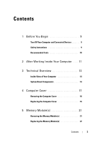
Computer and Connected Devices . . . . . 9 Safety Instructions 9 Recommended Tools 10 2 After Working Inside Your Computer . . . 11 3 Technical Overview 13 Inside View of Your Computer 13 System Board Components 14 4 Computer Cover 17 Removing the Computer Cover 18 Replacing the Computer - Dell Inspiron 660 | Owners Manual - Page 4
Cards 33 Removing PCI Express Cards 33 Replacing PCI Express Cards 35 Configuring Your Computer After Removing or Installing the PCI Express Card 37 9 Mini-Card 39 Removing the Mini-Card 40 Replacing the Mini-Card 41 10 Hard Drive(s 43 Removing the Hard Drive(s 43 Replacing the Hard Drive - Dell Inspiron 660 | Owners Manual - Page 5
(s 49 Removing the Optical Drive(s 49 Replacing the Optical Drives(s 53 12 Front I/O Panel 57 Removing the Front I/O Panel 57 Replacing the Front I/O Panel 59 13 Power Button Module 61 Removing the Power Button Module 61 Replacing the Power Button Module 63 14 Chassis Fan 65 Removing the - Dell Inspiron 660 | Owners Manual - Page 6
the Coin-Cell Battery 77 Replacing the Coin-Cell Battery 79 18 Power Supply 81 Removing the Power Supply 81 Replacing the Power Supply 83 19 System Board 85 Removing the System Board 85 Replacing the System Board 87 Entering the Service Tag in the BIOS 88 20 System Setup 91 Overview - Dell Inspiron 660 | Owners Manual - Page 7
21 Flashing the BIOS 107 22 Specifications 109 Contents 7 - Dell Inspiron 660 | Owners Manual - Page 8
8 Contents - Dell Inspiron 660 | Owners Manual - Page 9
shipped with your computer. For additional safety best practices information, see the Regulatory Compliance Homepage at dell.com/regulatory_compliance. WARNING: Disconnect all power sources before opening the computer cover or panels. After you finish working inside the computer, replace all covers - Dell Inspiron 660 | Owners Manual - Page 10
then unplug the cable from the network device. Recommended Tools The procedures in this document may require the following tools: • Small flat-blade screwdriver • Small Phillips screwdriver • Plastic scribe • Flash BIOS executable update program available at support.dell.com 10 Before You Begin - Dell Inspiron 660 | Owners Manual - Page 11
stray screws remain inside your computer • Connect any external devices, cables, cards, and any other part you removed before working on your computer • Connect your computer and all attached devices to their electrical outlets CAUTION: Before turning on your computer, replace all screws and ensure - Dell Inspiron 660 | Owners Manual - Page 12
12 After Working Inside Your Computer - Dell Inspiron 660 | Owners Manual - Page 13
regulatory_compliance. Inside View of Your Computer 3 2 1 4 5 6 10 1 power supply 3 secondary optical-drive 5 front I/O panel 7 secondary hard-drive 9 memory modules 7 8 9 2 primary optical-drive 4 front bezel 6 primary hard-drive 8 system board 10 card retention bracket Technical Overview 13 - Dell Inspiron 660 | Owners Manual - Page 14
System Board Components 1 2 3 45 23 22 21 20 19 18 17 16 15 14 6 7 8 9 10 13 12 11 14 Technical Overview - Dell Inspiron 660 | Owners Manual - Page 15
main power connector (ATX) 7 Mini-Card slot (MINI1) 8 power button reset jumper (PSWDCLR1) 17 front panel audio connector (AUDIOF1) 18 PCI Express x1 card slot (SLOT4) 19 PCI Express x1 card slot (SLOT3) 20 PCI Express x1 card slot (SLOT2) 21 battery socket (BT1) 22 PCI Express x16 card slot - Dell Inspiron 660 | Owners Manual - Page 16
16 Technical Overview - Dell Inspiron 660 | Owners Manual - Page 17
follow the steps in "Before You Begin" on page 9. For additional safety best practices information, see the Regulatory Compliance Homepage at dell.com/regulatory_compliance. CAUTION: Ensure that sufficient space exists to support the computer with the cover removed-at least 30 cm (1 ft.) of desk top - Dell Inspiron 660 | Owners Manual - Page 18
: Ensure that you remove the padlock from the padlock rings, if applicable. 1 Lay the computer on its side with the computer cover facing up. 2 Using a screwdriver, remove the screws that secure the computer cover to the chassis. 3 Release the computer cover by sliding it away from the front of the - Dell Inspiron 660 | Owners Manual - Page 19
the chassis. 4 Press the computer cover down and slide it towards the front of the computer. 5 Replace the screws that secure the computer cover to the chassis. 2 1 1 screws (2) 2 computer cover 6 Place the computer in an upright position. 7 Follow the instructions in "After Working Inside Your - Dell Inspiron 660 | Owners Manual - Page 20
20 Computer Cover - Dell Inspiron 660 | Owners Manual - Page 21
"Before You Begin" on page 9. For additional safety best practices information, see the Regulatory Compliance Homepage at dell.com/regulatory_compliance. Removing the Memory Module(s) Prerequisites Remove the computer cover. See "Removing the Computer Cover" on page 18. Procedure WARNING: The memory - Dell Inspiron 660 | Owners Manual - Page 22
Replacing the Memory Module(s) CAUTION: If you remove the original memory module(s) from your computer during a memory upgrade, keep them separate from any new memory module(s) that you may have, even if you purchased the new memory module(s) from Dell. If possible, do not pair an original memory - Dell Inspiron 660 | Owners Manual - Page 23
cutouts (2) 2 securing clips (2) (snapped in position) Postrequisites 1 Replace the computer cover. See "Replacing the Computer Cover" on page 19. 2 Follow the instructions in "After Working Inside Your Computer" on page 11. 3 Connect your computer and devices to electrical outlets, and then turn - Dell Inspiron 660 | Owners Manual - Page 24
24 Memory Module(s) - Dell Inspiron 660 | Owners Manual - Page 25
the steps in "Before You Begin" on page 9. For additional safety best practices information, see the Regulatory Compliance Homepage at dell.com/regulatory_compliance. Removing the Front Bezel Prerequisites Remove the computer cover. See "Removing the Computer Cover" on page 18. Front Bezel 25 - Dell Inspiron 660 | Owners Manual - Page 26
. 3 Rotate and pull the front bezel away from the front of the computer to release the front bezel clamps from the front panel slots. 1 2 3 4 5 1 front bezel 3 front bezel tabs (4) 5 front panel 2 front panel slots (4) 4 front bezel clamps (4) 4 Set aside the front bezel in a secure location - Dell Inspiron 660 | Owners Manual - Page 27
Replacing the Front Bezel Procedure 1 Align and insert the front bezel clamps into the front panel slots. 2 Rotate the front bezel towards the computer until the front bezel tabs snap into place. 1 2 3 4 1 front bezel 3 front panel slots (4) 5 front panel 5 2 front bezel tabs (4) 4 front bezel - Dell Inspiron 660 | Owners Manual - Page 28
Postrequisites 1 Replace the computer cover. See "Replacing the Computer Cover" on page 19. 2 Follow the instructions in "After Working Inside Your Computer" on page 11. 28 Front Bezel - Dell Inspiron 660 | Owners Manual - Page 29
You Begin" on page 9. For additional safety best practices information, see the Regulatory Compliance Homepage at dell.com/regulatory_compliance. Removing the Card Retention Bracket Prerequisites Remove the computer cover. See "Removing the Computer Cover" on page 18. Card Retention Bracket 29 - Dell Inspiron 660 | Owners Manual - Page 30
Procedure Push the release tab to release the card retention bracket from the chassis. 2 1 1 release tab 2 card retention bracket 30 Card Retention Bracket - Dell Inspiron 660 | Owners Manual - Page 31
Procedure Rotate and push the card retention bracket towards the computer until it snaps into place. Postrequisites 1 Replace the computer cover. See "Removing the Computer Cover" on page 18. 2 Follow the instructions in "After Working Inside Your Computer" on page 11. Card Retention Bracket 31 - Dell Inspiron 660 | Owners Manual - Page 32
32 Card Retention Bracket - Dell Inspiron 660 | Owners Manual - Page 33
page 9. For additional safety best practices information, see the Regulatory Compliance Homepage at dell.com/regulatory_compliance. Removing PCI Express Cards Prerequisites. 1 Remove the computer cover. See "Removing the Computer Cover" on page 18. 2 Remove the card retention bracket. See "Removing - Dell Inspiron 660 | Owners Manual - Page 34
any cables connected to the card, if applicable. 2 Remove the PCI Express card from the card slot: PCI Express x1 card - Grasp the card by its top corners, and ease it out of its connector. 1 2 1 PCI Express x1 card 2 PCI Express x1 card slot PCI Express x16 card - Push the securing tab to - Dell Inspiron 660 | Owners Manual - Page 35
it for your computer. 2 Replace the PCI Express card: PCI Express x1 card - Place the PCI Express card in the slot on the system board and press down firmly. Ensure that the PCI Express card is fully seated in the slot. 1 2 1 PCI Express x1 card 2 PCI Express x1 card slot PCI Express Cards 35 - Dell Inspiron 660 | Owners Manual - Page 36
to the equipment. 3 Replace the computer cover. See "Replacing the Computer Cover" on page 19. 4 Follow the instructions in "After Working Inside Your Computer" on page 11. 5 To complete the installation, see "Configuring Your Computer After Removing or Installing the PCI Express Card" on page 37 - Dell Inspiron 660 | Owners Manual - Page 37
, see the Quick Start Guide. For information on installing drivers and software for your card, see the documentation that shipped with the card. Sound card Network card Installed 1 Enter system setup. See "System Setup" on page 91. 2 Go to Onboard Audio Controller and then change the setting - Dell Inspiron 660 | Owners Manual - Page 38
38 PCI Express Cards - Dell Inspiron 660 | Owners Manual - Page 39
safety instructions that shipped with your computer. NOTE: Dell does not guarantee compatibility or provide support for Mini-Cards from sources other than Dell. If you ordered a wireless Mini-Card with your computer, the card is already installed. Your computer supports one half Mini-Card slot for - Dell Inspiron 660 | Owners Manual - Page 40
the Mini-Card Prerequisites Remove the computer cover. See "Removing the Computer Cover" on page 18. Procedure 1 Disconnect the antenna cable(s) from the Mini-Card. 2 Remove the screw that secures the Mini-Card to the system board. 2 1 1 antenna cables (2) 2 screw 3 Lift the Mini-Card away from - Dell Inspiron 660 | Owners Manual - Page 41
connector marked with a black triangle. • Connect the white cable to the connector marked with a white triangle. Postrequisites 1 Replace the computer cover. See "Replacing the Computer Cover" on page 19. 2 Follow the instructions in "After Working Inside Your Computer" on page 11. Mini-Card 41 - Dell Inspiron 660 | Owners Manual - Page 42
42 Mini-Card - Dell Inspiron 660 | Owners Manual - Page 43
and follow the steps in "Before You Begin" on page 9. For additional safety best practices information, see the Regulatory Compliance Homepage at dell.com/regulatory_compliance. WARNING: If you remove the hard drive from the computer when the drive is hot, do not touch the metal housing of the - Dell Inspiron 660 | Owners Manual - Page 44
a hard drive at a later time. 3 Remove the screws that secure the hard-drive assembly to the hard-drive bay. CAUTION: Ensure that you do not scratch the hard drive's circuit board, while removing or replacing the hard drive. 4 Lift the hard-drive assembly away from the computer. 44 Hard Drive(s) - Dell Inspiron 660 | Owners Manual - Page 45
Primary Hard-Drive 4 3 2 1 1 primary hard-drive assembly 3 power cable 2 data cable 4 screws (2) Hard Drive(s) 45 - Dell Inspiron 660 | Owners Manual - Page 46
Secondary Hard-Drive 4 3 2 1 1 secondary hard-drive assembly 3 power cable 2 data cable 4 screws (2) 46 Hard Drive(s) - Dell Inspiron 660 | Owners Manual - Page 47
the screws (one on each side) that secure the hard-drive brackets to the hard-drive. 6 Remove the hard-drive brackets off the hard drive. 1 3 2 1 hard drive 3 hard-drive bracket 2 screws (2) 7 If removing the hard drive changes the drive configuration, ensure that you reflect these changes in - Dell Inspiron 660 | Owners Manual - Page 48
data cables to the primary hard drive. 6 If you are replacing the secondary hard-drive: a Connect the power cable to the primary and secondary hard-drives. b Connect the data cable to the secondary hard-drive. Postrequisites 1 Replace the computer cover. See "Replacing the Computer Cover" on page 19 - Dell Inspiron 660 | Owners Manual - Page 49
in "Before You Begin" on page 9. For additional safety best practices information, see the Regulatory Compliance Homepage at dell.com/regulatory_compliance. Removing the Optical Drive(s) Prerequisites 1 Remove the computer cover. See "Removing the Computer Cover" on page 18. 2 Remove the front bezel - Dell Inspiron 660 | Owners Manual - Page 50
. 2 If you are removing the secondary optical-drive: a Disconnect the power cable from the primary and secondary optical-drives. b Disconnect the data cable from the secondary optical-drive. NOTE: If you are not replacing the optical drive at this time, disconnect the other end of the data cable - Dell Inspiron 660 | Owners Manual - Page 51
Primary Optical-Drive 4 3 2 1 1 power cable 3 primary optical-drive 2 data cable 4 screws (2) Optical Drive 51 - Dell Inspiron 660 | Owners Manual - Page 52
Secondary Optical-Drive 4 3 2 1 1 power cable 3 secondary optical-drive 2 data cable 4 screws (2) 5 Set aside the optical drive in a secure location. 52 Optical Drive - Dell Inspiron 660 | Owners Manual - Page 53
Replacing the Optical Drives(s) Procedure 1 Remove the screw from the optical drive you removed and insert it in the new optical drive. 1 screw 1 Optical Drive 53 - Dell Inspiron 660 | Owners Manual - Page 54
the chassis. 1 1 break-away metal plate 3 Gently slide the optical drive into the optical drive bay through the front of the computer. 4 Align the screw holes on the optical drive with the screw holes on the chassis. 5 Replace the screws that secure the optical drive to the chassis. 54 Optical - Dell Inspiron 660 | Owners Manual - Page 55
the data cable to the secondary optical-drive. Postrequisites 1 Replace the computer cover. See "Replacing the Computer Cover" on page 19. 2 Replace the front bezel. See "Replacing the Front Bezel" on page 27. 3 Follow the instructions in "After Working Inside Your Computer" on page 11. Optical - Dell Inspiron 660 | Owners Manual - Page 56
56 Optical Drive - Dell Inspiron 660 | Owners Manual - Page 57
in "Before You Begin" on page 9. For additional safety best practices information, see the Regulatory Compliance Homepage at dell.com/regulatory_compliance. Removing the Front I/O Panel Prerequisites 1 Remove the computer cover. See "Removing the Computer Cover" on page 18. 2 Remove the front bezel - Dell Inspiron 660 | Owners Manual - Page 58
. 2 Remove the screws that secure the front I/O panel to the front panel. 3 Slide the front I/O panel towards the side as shown in the illustration to release the clamps from the front panel and pull it away. 1 screws (2) 58 Front I/O Panel 2 1 2 front I/O panel - Dell Inspiron 660 | Owners Manual - Page 59
"System Board Components" on page 14. Postrequisites 1 Replace the front bezel see "Replacing the Front Bezel" on page 27. 2 Replace the computer cover. See "Replacing the Computer Cover" on page 19. 3 Follow the instructions in "After Working Inside Your Computer" on page 11. Front I/O Panel 59 - Dell Inspiron 660 | Owners Manual - Page 60
60 Front I/O Panel - Dell Inspiron 660 | Owners Manual - Page 61
"Before You Begin" on page 9. For additional safety best practices information, see the Regulatory Compliance Homepage at dell.com/regulatory_compliance. Removing the Power Button Module Prerequisites 1 Remove the computer cover. See "Removing the Computer Cover" on page 18. 2 Remove the front bezel - Dell Inspiron 660 | Owners Manual - Page 62
board connector (LEDH2). See "System Board Components" on page 14. 2 Press the power button module tabs and pull the power button module to release it from the front panel. 2 1 1 power button module 2 power button module tabs (4) 3 Set aside the power button module in a secure location. 62 - Dell Inspiron 660 | Owners Manual - Page 63
Board Components" on page 14. Postrequisites 1 Replace the front bezel. See "Replacing the Front Bezel" on page 27. 2 Replace the computer cover. See "Replacing the Computer Cover" on page 19. 3 Follow the instructions in "After Working Inside Your Computer" on page 11. Power Button Module 63 - Dell Inspiron 660 | Owners Manual - Page 64
64 Power Button Module - Dell Inspiron 660 | Owners Manual - Page 65
the steps in "Before You Begin" on page 9. For additional safety best practices information, see the Regulatory Compliance Homepage at dell.com/regulatory_compliance. Removing the Chassis Fan Prerequisites Remove the computer cover. See "Removing the Computer Cover" on page 18. Chassis Fan 65 - Dell Inspiron 660 | Owners Manual - Page 66
Board Components" on page 14. 2 Remove the screws that secure the chassis fan to the chassis. 3 Slide and lift the chassis fan away from the computer as shown in the illustration. 2 1 1 screws (4) 2 chassis fan 66 Chassis Fan - Dell Inspiron 660 | Owners Manual - Page 67
holes on the chassis. 2 Replace the screws that secure the chassis fan to the chassis. 3 Connect the chassis fan cable to the system board connector (FANSYS4). See "System Board Components" on page 14. Postrequisites Replace the computer cover. See "Replacing the Computer Cover" on page 19. Chassis - Dell Inspiron 660 | Owners Manual - Page 68
68 Chassis Fan - Dell Inspiron 660 | Owners Manual - Page 69
Begin" on page 9. For additional safety best practices information, see the Regulatory Compliance Homepage at dell.com/regulatory_compliance. Removing the Processor Fan and Heat-Sink Assembly Prerequisites Remove the computer cover. See "Removing the Computer Cover" on page 18. Processor Fan and - Dell Inspiron 660 | Owners Manual - Page 70
screws that secure the processor fan and heat-sink assembly to the system board. 3 Lift the processor fan and heat-sink assembly out of the computer. 3 2 1 1 processor fan cable 2 processor fan and heat-sink assembly 3 captive screws (4) 70 Processor Fan and Heat-Sink Assembly - Dell Inspiron 660 | Owners Manual - Page 71
cable to the system board connector (FANCPU). See "System Board Components" on page 14. Postrequisites 1 Replace the computer cover. See "Replacing the Computer Cover" on page 19. 2 Follow the instructions in "After Working Inside Your Computer" on page 11. Processor Fan and Heat-Sink Assembly 71 - Dell Inspiron 660 | Owners Manual - Page 72
72 Processor Fan and Heat-Sink Assembly - Dell Inspiron 660 | Owners Manual - Page 73
"Before You Begin" on page 9. For additional safety best practices information, see the Regulatory Compliance Homepage at dell.com/regulatory_compliance. Removing the Processor Prerequisites 1 Remove the computer cover. See "Removing the Computer Cover" on page 18. WARNING: Despite having a plastic - Dell Inspiron 660 | Owners Manual - Page 74
any objects to fall on the pins in the socket. 3 Open the processor cover and gently lift the processor from the processor socket. Leave the release lever extended in the release position so that the socket is ready for the new processor. 74 Processor - Dell Inspiron 660 | Owners Manual - Page 75
Replacing the Processor Procedure 1 Unpack the new processor, being careful not to touch the underside of the processor. CAUTION: You must position the processor correctly in the processor socket to avoid damage to the processor. 2 If the release lever on the socket is not fully extended, move it to - Dell Inspiron 660 | Owners Manual - Page 76
cover 6 processor cover notch Postrequisites 1 Replace the processor fan and heat-sink assembly. See "Replacing the Processor Fan and Heat-Sink Assembly" on page 71. 2 Replace the computer cover. See "Replacing the Computer Cover" on page 19. 3 Follow the instructions in "After Working Inside Your - Dell Inspiron 660 | Owners Manual - Page 77
Homepage at dell.com/regulatory_compliance. WARNING: A battery may explode if installed incorrectly. Replace the battery only with the same or equivalent type. Discard used batteries according to the manufacturer's instructions. CAUTION: Removing the coin-cell battery resets the BIOS settings to - Dell Inspiron 660 | Owners Manual - Page 78
Procedure 1 Locate the battery socket. See "System Board Components" on page 14. 2 Press the battery-release lever away from the battery until the coin-cell battery pops up. 1 3 2 1 battery-release lever 3 battery socket 2 coin-cell battery 3 Set aside the battery in a secure location. 78 - Dell Inspiron 660 | Owners Manual - Page 79
Postrequisites 1 Replace the computer cover. See "Replacing the Computer Cover" on page 19. 2 Follow the instructions in "After Working Inside Your Computer" on page 11. 3 Enter the system setup program and set the time and date. See "Entering System Setup" on page 91. 4 Update the BIOS settings - Dell Inspiron 660 | Owners Manual - Page 80
80 Coin-Cell Battery - Dell Inspiron 660 | Owners Manual - Page 81
the steps in "Before You Begin" on page 9. For additional safety best practices information, see the Regulatory Compliance Homepage at dell.com/regulatory_compliance. Removing the Power Supply Prerequisites Remove the computer cover. See "Removing the Computer Cover" on page 18. Power Supply 81 - Dell Inspiron 660 | Owners Manual - Page 82
drives. See "System Board Components" on page 14. 2 Remove the screws that secure the power supply to the chassis. 3 Press the power supply clamp to release the power supply from the chassis. 4 Slide and lift the power supply away from the chassis. 3 2 1 1 screws (4) 3 power supply clamp 2 power - Dell Inspiron 660 | Owners Manual - Page 83
screws that secure the power supply to the chassis. 4 Connect the DC power cables to the system board and drives. See "System Board Components" on page 14. Postrequisites 1 Replace the computer cover. See "Replacing the Computer Cover" on page 19. 2 Follow the instructions in "After Working Inside - Dell Inspiron 660 | Owners Manual - Page 84
84 Power Supply - Dell Inspiron 660 | Owners Manual - Page 85
Compliance Homepage at dell.com/regulatory_compliance. Removing the System Board Prerequisites 1 Remove the computer cover. See "Removing the Computer Cover" on page 18. 2 Remove the Mini-Card, if applicable. See "Removing the Mini-Card" on page 40. 3 Remove the any PCI-Express cards, if applicable - Dell Inspiron 660 | Owners Manual - Page 86
Procedure 1 Disconnect all cables connected to the system board. See "System Board Components" on page 14. Note the routing of all cables as you remove them so that you can re-route them correctly after installing the new system board. 2 Remove the screws that secure the system board to the chassis. - Dell Inspiron 660 | Owners Manual - Page 87
on page 22. 4 Replace any PCI-Express cards, if applicable. See "Replacing PCI Express Cards" on page 35. 5 Replace the Mini-Card, if applicable. See "Replacing the Mini-Card" on page 41. 6 Replace the computer cover. See "Replacing the Computer Cover" on page 19. 7 Follow the instructions in "After - Dell Inspiron 660 | Owners Manual - Page 88
Tag in the BIOS 1 Turn on the computer. 2 Press during POST to enter the system setup program. 3 Navigate to the main tab and enter the Service Tag in the Service Tag Input field. NOTE: The Service Tag Input field allows you to enter the Service Tag manually only when the Service Tag is absent - Dell Inspiron 660 | Owners Manual - Page 89
System Board 89 - Dell Inspiron 660 | Owners Manual - Page 90
90 System Board - Dell Inspiron 660 | Owners Manual - Page 91
computer, such as the amount of RAM, the size of the hard drive, screen information for future reference. Entering System Setup 1 Turn on (or restart) your computer. 2 During POST, when the DELL desktop. Then, turn off your computer and try again. See "Turn Off Your Computer and Connected Devices" on - Dell Inspiron 660 | Owners Manual - Page 92
features that define the configuration of your computer, including installed hardware, power conservation, and security features. Scroll up and down the list with the up- and down-arrow keys. As an option is highlighted, the Help Screen displays more information about that option and available - Dell Inspiron 660 | Owners Manual - Page 93
the current time in hh:mm:ss format System Date Displays the current date in mm/dd/yyyy format Service Tag Displays the Service Tag of the computer when the Service Tag is present Displays a field to input the Service Tag manually when the Service Tag is absent Asset Tag Displays the asset tag - Dell Inspiron 660 | Owners Manual - Page 94
installed on the SATA1 connector Displays the serial number of the device installed Displays the size of the device installed, if the device is a hard drive Displays the type of device installed on the SATA2 connector Displays the serial number of the device installed Displays the size of the device - Dell Inspiron 660 | Owners Manual - Page 95
Virtualization Technology Allows you to enable or disable the Intel virtualization feature for the processor Enabled or Disabled (Enabled by default) CPU XD Support Allows you to enable or disable the execute disable mode for the processor Enabled or Disabled (Enabled by default) Limit CPUID - Dell Inspiron 660 | Owners Manual - Page 96
computer Enabled or Disabled (Enabled by default) Advanced - Onboard Device Configuration Onboard Audio Controller Allows you to enable or disabled the audio controller Enabled or Disable (Enabled by default) SATA Mode Allows you to configure the operating mode of the integrated hard-drive - Dell Inspiron 660 | Owners Manual - Page 97
Boot (continued) USB Boot Support Boot Mode 1st Boot 2nd Boot 3rd Boot 4th Boot 5th Boot Allows you to enable or disable booting from USB mass storage devices such as hard drive, optical drive, USB key, and so on. Enabled or Disabled (Disabled by default) Specifies the boot sequence from the - Dell Inspiron 660 | Owners Manual - Page 98
Power (continued) Auto Power On Date Auto Power On Time Allows you to set the date on which the computer must turn on automatically; This option can be configured only if the Auto Power On mode is set to Enabled 1 to 31 (15 by default) Allows you to set the time at which the computer must turn on - Dell Inspiron 660 | Owners Manual - Page 99
Exit Save Changes and Reset Allows you to save changes and exit system setup Discard Changes and Reset Allows you to discard changes and exit system setup Load Default Allows you to restore the default settings System Setup 99 - Dell Inspiron 660 | Owners Manual - Page 100
operating system is on the floppy disk, the computer generates an error message. • Hard Drive - The computer attempts to boot from the primary hard drive. If no operating system is on the drive, the computer generates an error message. • CD/DVD/CD-RW Drive - The computer attempts to boot from the CD - Dell Inspiron 660 | Owners Manual - Page 101
to run Dell Diagnostics from the Drivers and Utilities disc. On completion of the diagnostic tests, the previous boot sequence is restored. 1 If you are booting from a USB device, connect the USB device to a USB port. 2 Turn on (or restart) your computer. 3 When F2 Setup, F12 Boot Options appears - Dell Inspiron 660 | Owners Manual - Page 102
safety instructions that shipped with your computer. WARNING: The computer must be disconnected from the electrical outlet to clear the password setting. CAUTION: Only a certified service technician should perform repairs on your computer. Damage due to servicing that is not authorized by Dell is - Dell Inspiron 660 | Owners Manual - Page 103
electrical outlets. 7 Remove the 2-pin jumper plug from pins 1 and 2 and replace it on pins 2 and 3 to enable the password feature. 8 Replace the computer cover. See "Replacing the Computer Cover" on page 19. 9 Connect your computer and devices to electrical outlets and turn them on. System Setup - Dell Inspiron 660 | Owners Manual - Page 104
safety instructions that shipped with your computer. WARNING: The computer must be disconnected from the electrical outlet to clear the password setting. CAUTION: Only a certified service technician should perform repairs on your computer. Damage due to servicing that is not authorized by Dell is - Dell Inspiron 660 | Owners Manual - Page 105
five seconds to clear the CMOS setting. 6 Remove the 2-pin jumper plug from pins 1 and 2 and replace it on pins 2 and 3. 7 Replace the computer cover. See "Replacing the Computer Cover" on page 19. 8 Connect your computer and devices to electrical outlets and turn them on. System Setup 105 - Dell Inspiron 660 | Owners Manual - Page 106
106 System Setup - Dell Inspiron 660 | Owners Manual - Page 107
require flashing when an update is available or when replacing the system board. To flash the BIOS: 1 Turn on the computer. 2 Go to support.dell.com/support/downloads. 3 Locate the BIOS update file for your computer: NOTE: The Service Tag for your computer is located on a label at the bottom of your - Dell Inspiron 660 | Owners Manual - Page 108
108 Flashing the BIOS - Dell Inspiron 660 | Owners Manual - Page 109
Specifications To learn about the features and advanced options available on your computer, see Specifications at support.dell.com/manuals Specifications 109 - Dell Inspiron 660 | Owners Manual - Page 110
110 Specifications
-
 1
1 -
 2
2 -
 3
3 -
 4
4 -
 5
5 -
 6
6 -
 7
7 -
8
-
9
-
10
-
11
-
12
-
13
-
14
-
15
-
16
-
17
-
18
-
19
-
20
-
21
-
22
-
23
-
24
-
25
-
26
-
27
-
28
-
29
-
30
-
31
-
32
-
33
-
34
-
35
-
36
-
37
-
38
-
39
-
40
-
41
-
42
-
43
-
44
-
45
-
46
-
47
-
48
-
49
-
50
-
51
-
52
-
53
-
54
-
55
-
56
-
57
-
58
-
59
-
60
-
61
-
62
-
63
-
64
-
65
-
66
-
67
-
68
-
69
-
70
-
71
-
72
-
73
-
74
-
75
-
76
-
77
-
78
-
79
-
80
-
81
-
82
-
83
-
84
-
85
-
86
-
87
-
88
-
89
-
90
-
91
-
92
-
93
-
94
-
95
-
96
-
97
-
98
-
99
-
100
-
101
-
102
-
103
-
104
-
105
-
106
-
107
-
108
-
109
-
110
 |
 |

Dell Inspiron 660
Owner’s Manual
Computer model: Inspiron 660
Regulatory model: D11M
Regulatory type: D11M002