Dell Inspiron Mini 12 1210 Inspiron Mini 12 Service Manual - Page 16
Replacing the Display Panel
 |
View all Dell Inspiron Mini 12 1210 manuals
Add to My Manuals
Save this manual to your list of manuals |
Page 16 highlights
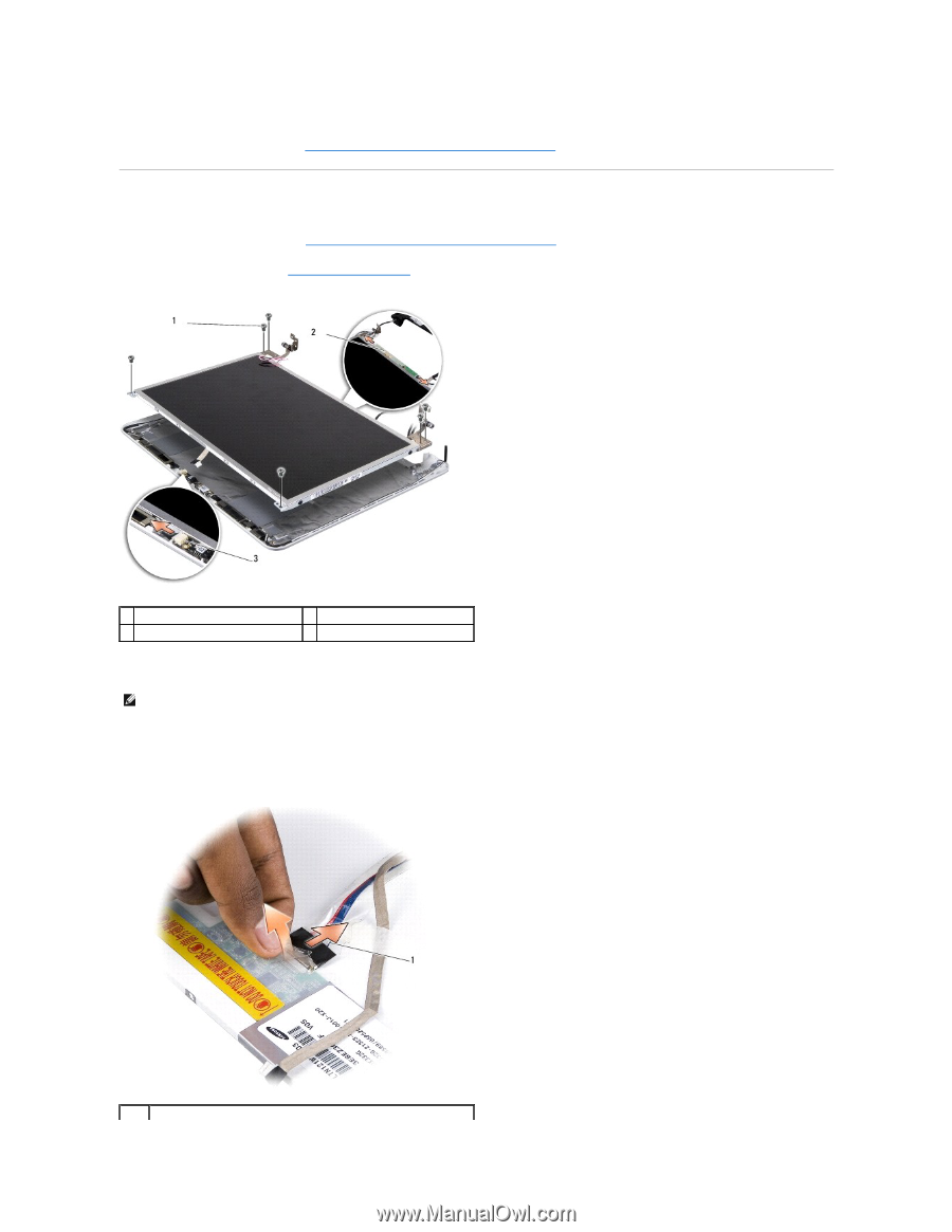
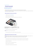
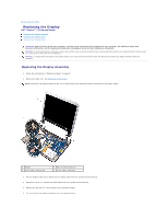
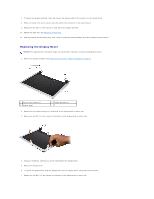
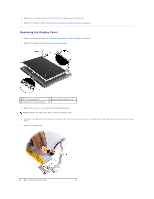
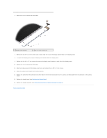
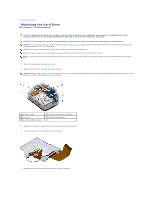
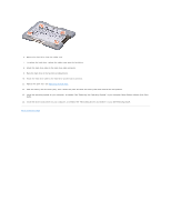
8. Replace the two rubber bumpers at the bottom of the display bezel on either side. 9. Replace the display assembly (see Follow the instructions in "Before You Begin" on page 9.). Replacing the Display Panel 1. Remove the display assembly (see Follow the instructions in "Before You Begin" on page 9.). 2. Remove the display bezel (see Replacing the Display Bezel). 1 M2.5 x 3-mm screws (6) 3 connector on the camera board 2 inverter board connectors (2) 3. Remove the six M2.5 x 3-mm screws securing the display panel. NOTE: Note how the cables have been routed to the display panel. 4. Disconnect the cables from the connectors on either side of the inverter board and the 2-in-1 camera and LVDS cable from the connector on the camera board. 5. Remove the display panel. 1 2-in-1 camera and LVDS cable
-
 1
1 -
2
-
3
-
4
-
5
-
6
-
7
-
8
-
9
-
10
-
 11
11 -
 12
12 -
 13
13 -
 14
14 -
 15
15 -
 16
16 -
 17
17 -
 18
18 -
 19
19 -
 20
20 -
 21
21 -
22
-
23
-
24
-
25
-
26
-
27
-
28
-
29
-
30
-
31
-
32
-
33
-
34
-
35
-
36
-
37
-
38
 |
 |