Dell Latitude D430 Service Manual - Page 28
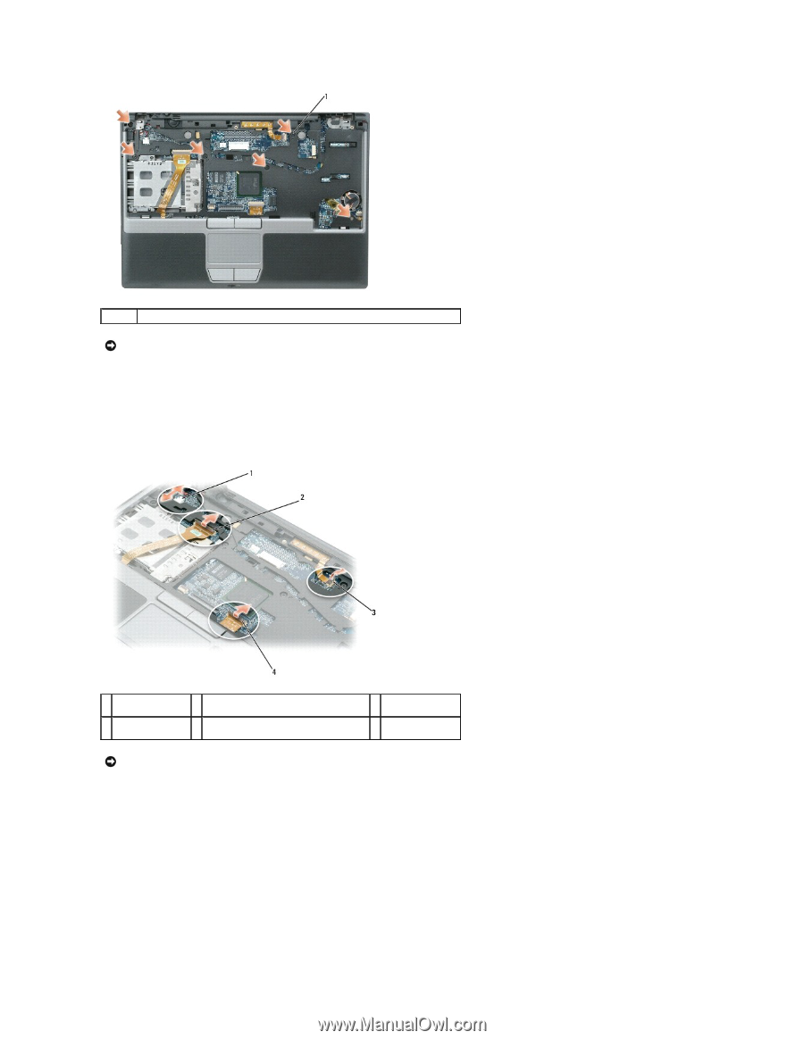
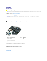
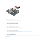
Pull on the plastic tab on top of the connectors to avoid damaging the connectors.
 |
View all Dell Latitude D430 manuals
Add to My Manuals
Save this manual to your list of manuals |
Page 28 highlights
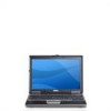
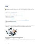
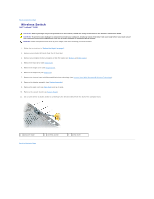
1 M2.5 x 5-mm screws (6) NOTICE: Pull on the plastic tab on top of the connectors to avoid damaging the connectors. 11. Disconnect the speaker connector from the system board. 12. Disconnect the Secure Digital/SIM card reader cable from the system board. 13. Disconnect the touch pad cable from the system board. 14. Lift the plastic bar on the LED board connector and disconnect the LED board cable from the system board. 1 speaker connector 2 Secure Digital/SIM card reader cable connector 4 touch pad connector 3 LED board connector NOTICE: Carefully separate the palm rest from the computer base to avoid damage to the palm rest. 15. Starting at the back center of the palm rest, use your fingers to separate the palm rest from the computer base by lifting the inside of the palm rest while pushing in on the outside.
-
 1
1 -
2
-
3
-
4
-
5
-
6
-
7
-
8
-
9
-
10
-
11
-
12
-
13
-
14
-
15
-
16
-
17
-
18
-
19
-
20
-
21
-
22
-
 23
23 -
 24
24 -
 25
25 -
 26
26 -
 27
27 -
 28
28 -
 29
29 -
 30
30 -
 31
31 -
 32
32 -
 33
33 -
34
-
35
-
36
-
37
 |
 |