Dell Latitude XFR D630 Service Manual - Page 53
Dimm B
 |
View all Dell Latitude XFR D630 manuals
Add to My Manuals
Save this manual to your list of manuals |
Page 53 highlights
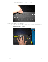
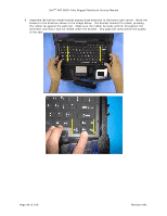
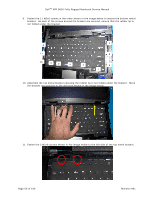
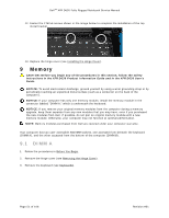
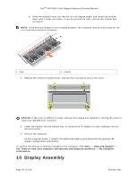
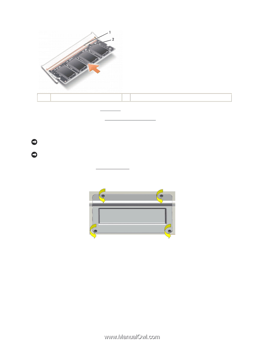
DellTM XFR D630 Fully Rugged Notebook Service Manual 1 tab 2 notch 6. Replace the keyboard (see Keyboards). 108H 7. Replace the hinge cover (see Installing the Hinge Cover). 109H 9.2 DIMM B NOTICE: If you need to install memory modules in two connectors, install a memory module in the connector labeled "DIMM A" before you install a module in the connector labeled "DIMM B." NOTICE: Insert memory modules at a 45-degree angle to avoid damaging the connector. 1. Follow the procedures in Before You Begin. 10H 2. Turn the computer bottom-side up, remove the 4 screws that secure the memory module cover, and then remove the cover. Page 53 of 106 Revision A01
-
 1
1 -
2
-
3
-
4
-
5
-
6
-
7
-
8
-
9
-
10
-
11
-
12
-
13
-
14
-
15
-
16
-
17
-
18
-
19
-
20
-
21
-
22
-
23
-
24
-
25
-
26
-
27
-
28
-
29
-
30
-
31
-
32
-
33
-
34
-
35
-
36
-
37
-
38
-
39
-
40
-
41
-
42
-
43
-
44
-
45
-
46
-
47
-
 48
48 -
 49
49 -
 50
50 -
 51
51 -
 52
52 -
 53
53 -
 54
54 -
 55
55 -
 56
56 -
 57
57 -
 58
58 -
59
-
60
-
61
-
62
-
63
-
64
-
65
-
66
-
67
-
68
-
69
-
70
-
71
-
72
-
73
-
74
-
75
-
76
-
77
-
78
-
79
-
80
-
81
-
82
-
83
-
84
-
85
-
86
-
87
-
88
-
89
-
90
-
91
-
92
-
93
-
94
-
95
-
96
-
97
-
98
-
99
-
100
-
101
-
102
-
103
-
104
-
105
-
106
 |
 |
Dell
TM
XFR D630 Fully Rugged Notebook Service Manual
Page 53 of 106
Revision A01
1
tab
2
notch
6.
Replace the keyboard (see
Keyboards
).
7.
Replace the hinge cover (see
Installing the Hinge Cover
).
9.2
DIMM B
NOTICE:
If you need to install memory modules in two connectors, install a memory module in
the connector labeled "DIMM A" before you install a module in the connector labeled "DIMM B."
NOTICE:
Insert memory modules at a 45-degree angle to avoid damaging the connector.
1.
Follow the procedures in
Before You Begin
.
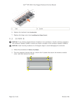
2.
Turn the computer bottom-side up, remove the 4 screws that secure the memory module
cover, and then remove the cover.