Dell PowerConnect W-AP175 Installation Guide
Dell PowerConnect W-AP175 Manual
 |
View all Dell PowerConnect W-AP175 manuals
Add to My Manuals
Save this manual to your list of manuals |
Dell PowerConnect W-AP175 manual content summary:
- Dell PowerConnect W-AP175 | Installation Guide - Page 1
Dell PowerConnect W-AP175 Outdoor Access Point Installation Guide The Dell PowerConnect W-AP175 is a resilient, environmentally hardened, outdoor rated, dual-radio, dual-band IEEE 802.11 a/b/g/n wireless access point. This outdoor access point is part of Dell's comprehensive wireless network - Dell PowerConnect W-AP175 | Installation Guide - Page 2
Installation Guide NOTE: Inform your supplier if there are any incorrect, missing, or damaged parts. If possible, retain the carton, including the original packing materials. Use these materials to repack and return the unit to the supplier if needed. 2 Dell PowerConnect W-AP175 Outdoor Access - Dell PowerConnect W-AP175 | Installation Guide - Page 3
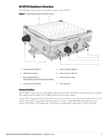
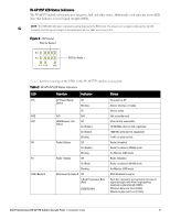
AP175. Figure 1 W-AP175 Overview (W-AP175P shown) 5 6 4 3 7 8 2 1 1 Antenna Interface (Radio 1) 2 USB Console Interface 3 Reserved (W-AP175P 1). R0 supports the 5 GHz frequency band and R1 supports the 2.4 GHz radio band. Dell PowerConnect W-AP175 Outdoor Access Point | Installation Guide 3 - Dell PowerConnect W-AP175 | Installation Guide - Page 4
by installing grounding lines. The ground connection must be complete before connecting power to the W-AP175 enclosure. Ensure that the resistance is less than 5 ohm between the ground termination point and the grounding tier. 4 Dell PowerConnect W-AP175 Outdoor Access Point | Installation Guide - Dell PowerConnect W-AP175 | Installation Guide - Page 5
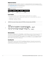
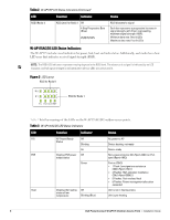
for Radio 1 Table 2 lists the meanings of the LEDs on the W-AP175P outdoor access point. Table 2 W-AP175P LED Status Indicators LED Function Indicator Status P/S POE ENT R0 R1 RSSI ( LEDs Maximum data rate: Four lit LEDs Dell PowerConnect W-AP175 Outdoor Access Point | Installation Guide 5 - Dell PowerConnect W-AP175 | Installation Guide - Page 6
Table 2 W-AP175P LED Status Indicators (Continued) LED RSSI (Radio 1) Function Indicator RSSI Level for Radio 1 Off 4 Step Progressive is not in heating status status of low temperature Blinking (Blue) Unit is pre-heating 6 Dell PowerConnect W-AP175 Outdoor Access Point | Installation Guide - Dell PowerConnect W-AP175 | Installation Guide - Page 7
results similar to an indoor deployment: a "dense" RF deployment that supports advanced Aruba features, such as ARM, efficient client roaming, and failover. construction, in mind when planning for an outdoor deployment. Dell PowerConnect W-AP175 Outdoor Access Point | Installation Guide 7 - Dell PowerConnect W-AP175 | Installation Guide - Page 8
of sight between the antennas Be cautious of trees or other foliage that may be near the path, or may grow and obstruct the path. 8 Dell PowerConnect W-AP175 Outdoor Access Point | Installation Guide - Dell PowerConnect W-AP175 | Installation Guide - Page 9
of the object must be added to the minimum clearance required for a clear radio line of sight. Consider the following simple example, illustrated in Figure 5. Dell PowerConnect W-AP175 Outdoor Access Point | Installation Guide 9 - Dell PowerConnect W-AP175 | Installation Guide - Page 10
frequencies. Always use a channel frequency that is furthest away from another signal. If radio interference is still a problem with your wireless bridge or mesh link, changing the antenna direction may improve the situation. 10 Dell PowerConnect W-AP175 Outdoor Access Point | Installation Guide - Dell PowerConnect W-AP175 | Installation Guide - Page 11
the known maximum wind velocity and direction at the site and be sure that any supporting structure, such as a pole, mast, or tower, is built to withstand this force. Lightning . Repeat this process for each antenna. Dell PowerConnect W-AP175 Outdoor Access Point | Installation Guide 11 - Dell PowerConnect W-AP175 | Installation Guide - Page 12
. For weatherproofing directly connected antennas, see "Weatherproofing Directly Connected Antennas" on page 15. For weatherproofing cable connections, see "Weatherproofing Cable Connections" on page 18. 12 Dell PowerConnect W-AP175 Outdoor Access Point | Installation Guide - Dell PowerConnect W-AP175 | Installation Guide - Page 13
Figure 6 Directly Connected Antennas Weep holes AP175_11 Dell PowerConnect W-AP175 Outdoor Access Point | Installation Guide 13 - Dell PowerConnect W-AP175 | Installation Guide - Page 14
, make the each layer of tape as flat as possible. Wrinkles and folds in the tape create places for water and moisture to gather. 14 Dell PowerConnect W-AP175 Outdoor Access Point | Installation Guide - Dell PowerConnect W-AP175 | Installation Guide - Page 15
Wrapping of Tape Pieces of tape as needed Wrap tape from just above knurled section to base of antenna mount Leave weep holes uncovered AP175_12 Dell PowerConnect W-AP175 Outdoor Access Point | Installation Guide 15 - Dell PowerConnect W-AP175 | Installation Guide - Page 16
Rubber Wrap Wrap rubber around base of antenna mount Squeeze to bond rubber to itself Rubber will be wrapped with 4 layers of tape AP175_14 16 Dell PowerConnect W-AP175 Outdoor Access Point | Installation Guide - Dell PowerConnect W-AP175 | Installation Guide - Page 17
of tape AP175_15 First and third layers wrap top to bottom 4. Repeat this process for all connectors. Second and final layers wrap bottom to top Dell PowerConnect W-AP175 Outdoor Access Point | Installation Guide 17 - Dell PowerConnect W-AP175 | Installation Guide - Page 18
to the cable's insulation. Figure 12 First Wrapping of Tape Wrap tape from antenna connector base to cable Pieces of tape as needed AP175_17 18 Dell PowerConnect W-AP175 Outdoor Access Point | Installation Guide - Dell PowerConnect W-AP175 | Installation Guide - Page 19
14 Butyl Rubber Wrap Wrap rubber around connector and cable Squeeze to bond rubber to itself Rubber will be wrapped with 4 layers of tape AP175_19 Dell PowerConnect W-AP175 Outdoor Access Point | Installation Guide 19 - Dell PowerConnect W-AP175 | Installation Guide - Page 20
process for all connectors. Second and final layers wrap bottom to top Installing the W-AP175 The W-AP175 can be installed on a wall or attached to a pole. The following section earthquake, electric power, and transportation. 20 Dell PowerConnect W-AP175 Outdoor Access Point | Installation Guide - Dell PowerConnect W-AP175 | Installation Guide - Page 21
the AP 2. Attach the mounting bracket (with W-AP175) on the pole using four M8 x110 bolts (with flat washers, spring washers and nuts) and the pair of pole anchors. Figure 17 Attaching the mounting bracket to the pole AP175_03 Dell PowerConnect W-AP175 Outdoor Access Point | Installation Guide 21 - Dell PowerConnect W-AP175 | Installation Guide - Page 22
of the mounting bracket and tighten the expansion screws. 5. Attach the W-AP175 to the mounting bracket by inserting the two M6 x30 bolts (with flat and spring washers) through the installation holes, and tighten the bolts. 22 Dell PowerConnect W-AP175 Outdoor Access Point | Installation Guide - Dell PowerConnect W-AP175 | Installation Guide - Page 23
the bare grounding cable into the copper lug, and press firmly with the crimping pliers. 2. Fasten the copper lug to the grounding hole on the W-AP175 with the M4 x12 bolt and external-tooth washer. Dell PowerConnect W-AP175 Outdoor Access Point | Installation Guide 23 - Dell PowerConnect W-AP175 | Installation Guide - Page 24
Connecting the Ethernet Cable (W-AP175P) To ensure that your outdoor access point (AP) maintains ethernet connectivity and Power over Ethernet 11. Water-proof the ethernet cable connection with electrical tape and butyl rubber. 24 Dell PowerConnect W-AP175 Outdoor Access Point | Installation Guide - Dell PowerConnect W-AP175 | Installation Guide - Page 25
ethernet cable connector into the ethernet interface and hand-tighten the locknut. 15. Water-proof the ethernet cable connection with electrical tape and butyl rubber. Dell PowerConnect W-AP175 Outdoor Access Point | Installation Guide 25 - Dell PowerConnect W-AP175 | Installation Guide - Page 26
23 Connecting the Ethernet cable Connecting the Power Cable (W-AP175 AC/DC) CAUTION: Installation and service of Dell products should be performed by Professional Installers. The W- tape, adhesive insulation tape and strap. 26 Dell PowerConnect W-AP175 Outdoor Access Point | Installation Guide - Dell PowerConnect W-AP175 | Installation Guide - Page 27
Attaching the Solar Shield to the W-AP175 Attach the solar shield to the W-AP175 by using the four M4 x16 (with flat and spring washers). Figure 24 Attaching the Solar Shield to the AP AP175_08 AP175_07 Dell PowerConnect W-AP175 Outdoor Access Point | Installation Guide 27 - Dell PowerConnect W-AP175 | Installation Guide - Page 28
(supports MIMO) Feeder cable may be used for external antenna deployments Visual Status Indicators (LEDs): See Table 2 Electrical Power In W-AP175P: 48-volt DC model only) Antenna: 4 x N-Type female antenna interfaces 28 Dell PowerConnect W-AP175 Outdoor Access Point | Installation Guide - Dell PowerConnect W-AP175 | Installation Guide - Page 29
(OFDM) 802.11n: 2x2 MIMO with two spatial streams Supported modulation types: 802.11b: BPSK, QPSK, CCK 802. Mbps to 300 Mbps) 802.11n high-throughput (HT) support: HT 20/40 802.11n packet aggregation: A-MPDU, A-MSDU Dell PowerConnect W-AP175 Outdoor Access Point | Installation Guide 29 - Dell PowerConnect W-AP175 | Installation Guide - Page 30
energy and, if not installed and used in accordance with the instructions, may cause harmful interference to radio communications. However, there is of Country Specific Regulations please speak with your Dell Representative. 30 Dell PowerConnect W-AP175 Outdoor Access Point | Installation Guide - Dell PowerConnect W-AP175 | Installation Guide - Page 31
Directive. China RoHS Dell products also comply with China environmental declaration requirements and are labeled with the "EFUP 25" label shown at the left. TRA REGISTERED No: ER0055290/11 DEALER No: DA0039425/10 200202320G Dell PowerConnect W-AP175 Outdoor Access Point | Installation Guide 31 - Dell PowerConnect W-AP175 | Installation Guide - Page 32
this action and indemnifies, in full, Aruba Networks, Inc. from any and all legal actions that might be taken against it with respect to infringement of copyright on behalf of those vendors. Dell PowerConnect W-AP175 Outdoor Access Point | Installation Guide Part Number 0511047-01 | January 2012
-
 1
1 -
 2
2 -
 3
3 -
 4
4 -
 5
5 -
 6
6 -
 7
7 -
8
-
9
-
10
-
11
-
12
-
13
-
14
-
15
-
16
-
17
-
18
-
19
-
20
-
21
-
22
-
23
-
24
-
25
-
26
-
27
-
28
-
29
-
30
-
31
-
32
 |
 |
Dell PowerConnect W-AP175 Outdoor Access Point
Installation Guide
0511047-01
| January 2012
1
The Dell PowerConnect W-AP175 is a resilient, environmentally hardened, outdoor rated, dual-radio, dual-band
IEEE 802.11 a/b/g/n wireless access point. This outdoor access point is part of Dell’s comprehensive wireless
network solution. The W-AP175 works only in conjunction with an Dell PowerConnect W-Series controller and
each AP can be centrally managed, configured, and upgraded through the controller.
There are three versions of the W-AP175, which mainly differ in the way they receive power.
W-AP175P: PoE+ powered (802.3at)
W-AP175AC: AC powered (100-240 V AC)
W-AP175DC: DC powered (12-48 V DC)
Guide Overview
“W-AP175 Hardware Overview” on page
3
provides a detailed hardware overview of the three W-AP175
models.
“Outdoor Planning and Deployment Considerations” on page
7
provides key questions to ask and items to
consider when deploying an outdoor wireless network.
“Installing Antennas” on page
11
describes how to installing antennas.
“Weatherproofing Connections” on page
12
provides instructions on weatherproofing the AP’s connectors.
“Installing the W-AP175” on page
20
describes the multi-step process for a successful installation and
deployment of an W-AP175.
“Safety and Regulatory Compliance” on page
30
provides an overview of safety and regulatory compliance
information.
W-AP175 Operations
Wireless access point (IEEE 802.11 a/b/g/n)
Wireless air monitor (IEEE 802.11 a/b/g/n)
Enterprise mesh point
Enterprise mesh portal
Protocol-independent networking functionality
W-AP175P: IEEE 802.3at Power over Ethernet+ (PoE+) compatible
W-AP175AC and W-AP175DC: IEEE 802.3af Power Sourcing Equipment (PSE) device
NOTE:
The W-AP175P requires ArubaOS 5.0.2.1 or later. The W-AP175AC and W-AP175DC require ArubaOS 6.1.2.3 or later.
NOTE:
The W-AP175AC/DC can function as a Power Sourcing Equipment (PSE) device by providing power through its ethernet
port in compliance with the IEEE 802.3af standard.