Dell PowerConnect W-IAP3WN Installation Guide - Page 1
Dell PowerConnect W-IAP3WN Manual
 |
View all Dell PowerConnect W-IAP3WN manuals
Add to My Manuals
Save this manual to your list of manuals |
Page 1 highlights
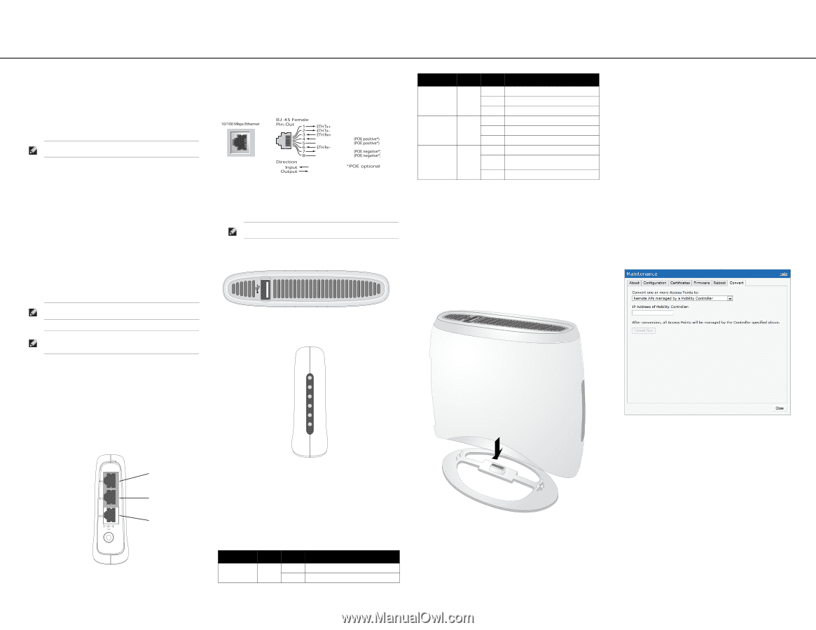
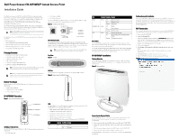
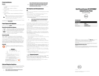
Dell PowerConnect W-IAP3WN/P Instant Access Point Installation Guide The Dell PowerConnect W-IAP3WN and W-IAP3WNP are single-radio, singleband wireless access points (AP) that support the IEEE 802.11n standard for highperformance WLAN. These access points use MIMO (Multiple-in, Multiple-out) technology and other high-throughput mode techniques to deliver highperformance, 802.11n 2.4 GHz functionality while simultaneously supporting existing 802.11 b/g wireless services. The W-IAP3WN/P ships with Dell Instant software will operate as an Instant AP. However, the W-IAP3WN/P can be converted to operate as a Remote AP (RAP). For information about the IAP to RAP conversion, see RAP Conversion. Note: The W-IAP3WN/P requires Dell Instant 3.1 to operate as a Instant AP and WSeries ArubaOS 6.2.x to operate as a Remote AP. The Dell PowerConnect W-IAP3WN/P Series access points provide the following capabilities: Wireless transceiver Protocol-independent networking functionality IEEE 802.11b/g/n operation as a wireless access point IEEE 802.11b/g/n operation as a wireless air monitor Compatibility with IEEE 802.3af PoE Package Contents 1x W-IAP3WN or W-IAP3WNP Access Point 1x Installation Guide (this document) 1x Dell Instant Quick Start Guide 1x RJ-45 Ethernet Cable 1x 12V Power Adapter (W-IAP3WN only) 1x 48V Power Adapter (W-IAP3WNP only) Note: The 48V power adapter that ships with the W-IAP3WNP does not come with a country specific power cord. This cord must be ordered separately. Note: Inform your supplier if there are any incorrect, missing, or damaged parts. If possible, retain the carton, including the original packing materials. Use them to repack the product in case there is a need to return it. Before You Begin Before installing your W-IAP3WN/P Remote Access Point, please ensure you have the following: W-IAP3WN/P (included) 1 x RJ-45 Ethernet Cable (included) 1 x Power Adapter (included) W-IAP3WN/P Overview Figure 1 Rear View (W-IAP3WNP Shown) E1: LAN port (middle) E2: LAN port (bottom) On the W-IAP3WNP, port E2 has PoE power sourcing capability (PSE) to supply power to any compliant 802.3af powered device (class 0-4). Figure 2 Fast Ethernet Port Pin Out DC IN (Power Socket) The W-IAP3WN/P power adapter (included) connects to the DC IN port. The W-IAP3WN/P does not have an On/Off switch. The device turns on when the power adapter is attached and plugged into a power outlet. The device turns off when you disconnect the power adapter from the power source (outlet). Note: The W-IAP3WN ships with a 12V power supply and the W-IAP3WNP ships with a 48V power supply. These power supplies are not interchangeable. Top View Figure 3 Top View USB Port The W-IAP3WN/P is equipped with a USB port to support cellular modems. Figure 4 Bottom View (W-IAP3WNP Shown) Pwr E0 E1 E2 WLAN PSE 48V 0.75A E0 (WAN port) E1 (LAN port) E2 (LAN port) 10/100Base-T Ethernet Ports The W-IAP3WN/P has three 10/100Base-T (RJ-45) Ethernet ports for wired network connectivity. E0: WAN port (top) LEDs The W-IAP3WN has five LED indicators that display the status of the device. The W-IAP3WNP has an additional LED called PSE. PWR: When lit, the W-IAP3WN/P is powered on E0:Indicates activity and/or status on this port. E1: Indicates activity and/or status on this port E2: Indicates activity and/or status on this port WLAN: Indicates wireless status and activity PSE (W-IAP3WNP only): Indicated the PSE status on the W-IAP3WNP LED Color(s) Activity Action PWR Green On Off Power on No power LED WLAN Ports (E0, E1, E2) PSE Color(s) Activity Action Green Green Green Off On Flashing Off On Flashing Off On Flashing Wireless is inactive Wireless is active Radio mode No link Link established Ethernet activity Not sourcing PoE power Sourcing PoE power to an 802.3af Powered Device PoE power sourcing error Reset Button The W-IAP3WN/P is equipped with reset button, that when pushed, resets the device to factory default settings. The reset button is located on the bottom of the device and is recessed in a small, round hole. To reset the W-IAP3WN/P, insert a small, narrow object, such as a pin or paperclip, into the hole and press and hold the button while powering on the W-IAP3WN/P. This will return the device to factory default settings. W-IAP3WN/P Installation Tabletop Mounting The W-IAP3WN/P is shipped with a stand to use on flat (i.e. table top) surfaces. Place the W-IAP3WN/P in the stand (see Figure 5) and place the stand on a flat, levelled surface. Figure 5 Stand Installation Connecting the Required Cables The W-IAP3WN/P must be connected to a network device that has access to the Internet, such as a router or modem. To complete the installation of the W-IAP3WN/P: 1. Connect one end of the provided RJ-45 cable to port E0 on the W-IAP3WN/P. 2. Connect the other end of the RJ-45 cable to a free RJ-45 port on your modem or router. 3. Attach the provided power adapter to the DC IN port on the W-IAP3WN/P. 4. Connect the other end of the power adapter to a power outlet. The W-IAP3WN/P is now powered on. To verify this, ensure that the PWR LED lit is solid green. Verifying Successful Installation Once the W-IAP3WN/P's PWR LED is lit, the device will take 2 to 3 minutes to complete the boot cycle. Once the boot cycle is complete, the access point is operational. If the Instant access point provided to you has not been configured, see the included Dell Instant Quick Start Guide or the instructions provided by your network administrator. RAP Conversion If your network administrator has instructed you to convert the W-IAP3WN/P to work in RAP mode, follow the process below to complete the RAP conversion. 1. Power up the W-IAP3WN/P. 2. Connect to Instant SSID. 3. Login to the W-IAP3WN/P by navigating to instant.dell.com and login to the Instant WebUI. The default username is admin and the default password is admin. See the included Dell Instant Quick Start Guide for more information. 4. Navigate to the Maintenance tab in the top right. 5. Click on the Convert tab. 6. Select Remote APs managed by a Mobility Controller from the drop down menu. 7. Enter the IP address of the controller. This is provided by your network administrator. 8. Click Convert Now to complete the conversion (see Figure 6). 9. The W-IAP3WN/P will reboot and begin operating in RAP mode. Figure 6 IAP-RAP Conversion over the Internet
-
 1
1 -
 2
2
 |
 |