Dell PowerEdge 2550 Rack Installation Guide
Dell PowerEdge 2550 Manual
 |
View all Dell PowerEdge 2550 manuals
Add to My Manuals
Save this manual to your list of manuals |
Dell PowerEdge 2550 manual content summary:
- Dell PowerEdge 2550 | Rack Installation Guide - Page 1
Dell™ Systems RACK INSTALLATION GUIDE www.dell.com support.dell.com - Dell PowerEdge 2550 | Rack Installation Guide - Page 2
to hardware or loss of data and tells you how to avoid the problem. CAUTION: A CAUTION indicates a potentially hazardous situation which, if not avoided Dell Computer Corporation is strictly forbidden. Trademarks used in this text: Dell, the DELL logo, PowerEdge, and RapidRails are trademarks of Dell - Dell PowerEdge 2550 | Rack Installation Guide - Page 3
for specific warning and/or caution statements and procedures. Servers, storage systems, and appliances are considered to be components in a rack. Thus, "component" refers to any server, storage system, or appliance, as well as to various peripherals or supporting hardware. WARNING: Installing Dell - Dell PowerEdge 2550 | Rack Installation Guide - Page 4
pinch your fingers. • After a component is inserted into the rack, carefully extend the rail into a locking position, and then slide the component into the rack. • Do not overload the AC supply branch circuit that provides power to the rack. The total rack load should not exceed 80 percent of the - Dell PowerEdge 2550 | Rack Installation Guide - Page 5
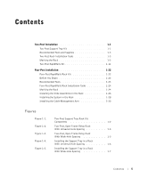
Two-Post Installation 1-1 Two-Post Support Tray Kit 1-1 Recommended Tools and Supplies 1-3 Two-Post Rack Installation Tasks Figures Figure 1-1. Figure 1-2. Figure 1-3. Figure 1-4. Figure 1-5. Two-Post Support Tray Rack Kit Components 1-2 Two-Post, Open-Frame Relay Rack With Universal - Dell PowerEdge 2550 | Rack Installation Guide - Page 6
Brackets to the Support Tray 1-8 Installing the Support Tray in a Rack With Universal-Hole Spacing 1-9 Installing the Support Tray in a Contents . . 1-23 One Rack Unit 1-24 Using the Template to Mark Vertical Rails 1-25 Installing the Slide Assemblies 1-27 Installing the System in the Rack . - Dell PowerEdge 2550 | Rack Installation Guide - Page 7
guide provides instructions for trained service technicians installing one or more Dell™ systems in a Dell rack. One rack kit is required for each system installed in the rack. This guide configuration. Two-Post Support Tray Kit The two-post support tray kit is used to install a Dell system in a two - Dell PowerEdge 2550 | Rack Installation Guide - Page 8
mount brackets • One 2-U two-post template Figure 1-1. Two-Post Support Tray Rack Kit Components center-mount brackets (2) support tray 10-32 x 0.375-inch truss-head Phillips screw (8) #10 internal-star washer (8) 1-2 Rack Installation Guide 12-24 x 0.5-inch pan-head Phillips screw (4) 2-U two - Dell PowerEdge 2550 | Rack Installation Guide - Page 9
tools and supplies to install 1 Determine where you want to place the bottom of the support tray. If you are installing other components in the rack, . 2 Place the 2-U template over the front of the rack rails in the desired location. 3 Position the bottom of the template in Installation Guide 1-3 - Dell PowerEdge 2550 | Rack Installation Guide - Page 10
dell.com | support.dell.com Figure 1-2. Two-Post, Open-Frame Relay Rack With Universal-Hole Spacing 3.5 inches (2 U) 1.75 inch (1 .625 .5 inch .625 5 If your rack has wide-hole spacing (see Figure 1-3), mark the lower and middle mounting positions on the vertical rails Rack Installation Guide - Dell PowerEdge 2550 | Rack Installation Guide - Page 11
support tray kit, but it does not use the center-mount brackets. 1 Place the support tray into the rack with the bottom of the tray at the marks you made support tray's front mounting bracket flush against the 2-post rack. 2 If you are installing the support to secure the support tray using the upper - Dell PowerEdge 2550 | Rack Installation Guide - Page 12
www.dell.com | support.dell.com Figure 1-4. Installing the Support Tray in a Rack With Universal-Hole Spacing 12-24 x 0.5-inch pan-head Phillips screws (4) R 3 If you are installing the support tray in a rack with wide-hole spacing, install the four 12-24 x 0.5-inch pan-head Phillips screws - Dell PowerEdge 2550 | Rack Installation Guide - Page 13
side so that it faces the stamped "L" on the left side of the support tray. Ensure that the four holes on the side of the bracket align with four matching holes on the left side of the support tray. 2 Secure the left-hand, center-mount bracket to the support tray using four 10-32 x 0.375-inch truss - Dell PowerEdge 2550 | Rack Installation Guide - Page 14
www.dell.com | support.dell.com Figure 1-6. Installing the Center-Mount Brackets to the Support Tray L R 10-32 x 0.375-inch truss-head Phillips screws, eachwith a #10 star washer (4) 3 Install the right-hand, center-mount bracket to the right side of the support tray by repeating steps 1 and 2. - Dell PowerEdge 2550 | Rack Installation Guide - Page 15
in a Rack With Universal-Hole Spacing 12-24 x 0.5-inch pan-head Phillips screws (4) 6 If you are installing the support tray onto a wide-hole spacing relay rack with the bottom of the support tray positioned at the place you marked on the rack, install the screws finger tight into the bottom and the - Dell PowerEdge 2550 | Rack Installation Guide - Page 16
into a rack is identical for flush-mounted and center-mounted support trays. 1 If your system has a bezel, remove it (see the system Installation and Troubleshooting Guide for instructions). 2 Lift the system into position on the support tray. 3 Slide the system completely into position and secure - Dell PowerEdge 2550 | Rack Installation Guide - Page 17
available, to the system (see the system Installation and Troubleshooting Guide for instructions). You have completed the installation of the two-post support which enable the system to be pulled out of the rack cabinet for servicing. You must properly secure the two-post, open-frame relay rack to - Dell PowerEdge 2550 | Rack Installation Guide - Page 18
www.dell.com | support.dell.com See "Safety Instructions" at the front of this document for additional safety information regarding rack installation. Rack Kit Contents The assemblies (2) template 12-24 x 0.5-inch pan-head Phillips screw (8) cable-management arm 1-12 Rack Installation Guide - Dell PowerEdge 2550 | Rack Installation Guide - Page 19
and supplies to install the system in a two-post open-frame relay rack: • #2 Phillips screwdriver • 3/8-inch nut driver • the rack. 2 Place the 2-U template over the front of the rack rails in the desired location. 3 Position the bottom of the template in line 1-2). Rack Installation Guide 1-13 - Dell PowerEdge 2550 | Rack Installation Guide - Page 20
dell.com | support.dell.com 5 If your rack has wide hole spacing (see Figure 1-3), mark the lower and middle mounting positions on the vertical rails rack kit is designed to support a single system in 3/8-inch nut driver, loosen by Using a 3/8-inch nut driver, tighten the locking nuts on - Dell PowerEdge 2550 | Rack Installation Guide - Page 21
right slide assembly to the right of the left slide assembly. Position both rails so that the center brackets are facing upwards. NOTE: The slide assemblies are , you must remove, rotate 180 degrees, and reinstall the mounting bracket on the opposite slide assembly. 2 Remove two locking nuts - Dell PowerEdge 2550 | Rack Installation Guide - Page 22
dell.com | support.dell. assemblies using the two shoulder washers and two locking nuts you removed in step 2 (see Figure 1-12). Figure 1-12. rack. 7 The guide pin on the mounting flange should enter a mounting hole in the rack (see Figure 1-13). 8 Use a 3/8-inch nut driver to fully tighten the - Dell PowerEdge 2550 | Rack Installation Guide - Page 23
1-13. Installing the Slide Assemblies for Flush-Mount Configuration guide pin 12-24 x 0.5-inch pan-head Phillips screws each slide assembly. Installing the System in the Rack CAUTION: Due to the size and weight of the computer system, never attempt to install the computer system by yourself. NOTE: - Dell PowerEdge 2550 | Rack Installation Guide - Page 24
www.dell.com | support.dell.com 1 Pull the inner slides out to their fully extended position. 2 If your system has an optional bezel, remove it (see the system Installation and Troubleshooting Guide for instructions). CAUTION: Because of the size and weight of the system, never attempt to install - Dell PowerEdge 2550 | Rack Installation Guide - Page 25
the front panel (see Figure 1-15). Figure 1-15. Securing the System in the Rack (Flush-Mount Configuration) captive screw (2) 9 Attach the front bezel, if you removed it. Rack Installation Guide 1-19 - Dell PowerEdge 2550 | Rack Installation Guide - Page 26
dell.com | support.dell.com Installing the Cable Management Arm 1 Facing the back of the two-post rack, locate the two slots and the threaded hole on the back right side of the system. 2 Insert the bracket on the end end of the cable-management arm (the end on the free end of the cable-management - Dell PowerEdge 2550 | Rack Installation Guide - Page 27
you connected in step 4 through the slots of the strain-relief bracket. b Insert the ends of the four long portions of the strain-relief bracket into the four matching holes beside the Velcro strap cables to expansion cards strain-relief bracket captive thumbscrew Rack Installation Guide 1-21 - Dell PowerEdge 2550 | Rack Installation Guide - Page 28
details, see your system's Installation and Troubleshooting Guide or the User's Guide. 8 Secure the cables to the cable-management arm: a After connecting the cables to the system, unscrew the thumbscrews that secure the front of the server to the front vertical rail. b Slide the system forward to - Dell PowerEdge 2550 | Rack Installation Guide - Page 29
you begin installing your system in the rack, carefully read the safety instructions found earlier in this guide. If you have a Dell PowerEdge™ 4210 rack, see the procedures in the Dell PowerEdge 4210 Rack Installation Guide. Recommended Tools Although no tools are required to install the rack kit - Dell PowerEdge 2550 | Rack Installation Guide - Page 30
rack, see the Dell Rack Advisor software available on the Dell Web site at http://support.dell.com. CAUTION: If you are installing more than one system, install the slide assemblies so that the first system is installed in the lowest available position in the rack. 1-24 Rack Installation Guide - Dell PowerEdge 2550 | Rack Installation Guide - Page 31
of the template on the vertical rails at the front of the rack template front. 2 Mark the rack's front vertical rails with a felt-tipped marker or place self- see Figure 1-19). 3 Make a mark or place tape on the vertical rails next to the template's V-shaped notches that are marked in red. Figure - Dell PowerEdge 2550 | Rack Installation Guide - Page 32
dell.com | support.dell.com Installing the Slide Assemblies in the Rack NOTE: If Dell align with the marks you made from the V-shaped notches in rail (see Figure 1-20). 4 Push forward until the mounting tabs are secure in the square holes on the vertical rail rail. 6 Repeat steps 1 through - Dell PowerEdge 2550 | Rack Installation Guide - Page 33
Figure 1-21. Installing the Slide Assemblies push-button mounting tabs slide-assembly mounting-bracket flange slide assembly (2) front of rack Rack Installation Guide 1-27 - Dell PowerEdge 2550 | Rack Installation Guide - Page 34
www.dell.com | support.dell.com Installing the System in the Rack The subsections that follow include instructions for installing the system in the rack. CAUTION: If you are installing more than one system, install the first system in the lowest available position in the rack. Never pull more than - Dell PowerEdge 2550 | Rack Installation Guide - Page 35
up on the green latches and push the chassis into the rack. 8 Tighten the captive thumbscrews on each side of the front chassis panel. 9 If available, install the optional front bezel. Rack Installation Guide 1-29 - Dell PowerEdge 2550 | Rack Installation Guide - Page 36
dell.com | support.dell.com Installing the Cable-Management Arm 1 Facing the back of the rack cabinet, locate the threaded hole on the back of the slide assembly and secure the end of the cable-management arm (the end having a bracket and thumbscrew) to the right side vertical rail free end of the - Dell PowerEdge 2550 | Rack Installation Guide - Page 37
you connected in step 4 through the slots of the strain-relief bracket. b Insert the ends of the four long portions of the strain-relief bracket into the four matching holes beside the Velcro strap cables to expansion cards strain-relief bracket captive thumbscrew Rack Installation Guide 1-31 - Dell PowerEdge 2550 | Rack Installation Guide - Page 38
details, see your system's Installation and Troubleshooting Guide or the User's Guide. 7 Secure the cables to the cable-management arm: a After connecting the cables to the system, unscrew the thumbscrews that secure the front of the server to the front vertical rail. b Slide the system forward to - Dell PowerEdge 2550 | Rack Installation Guide - Page 39
1-30 routing cables, 1-22 cables, 1-22, 1-32 routing, 1-32 D Dell Web site, 1-24 F four-post RapidRails kit contents, 1-22 installing cable kit, 1-23 two-post RapidRails kit, 1-13 two-post support tray kit, 1-3 two-post RapidRails kit, 1-11 support tray kit, 1-1 two-post rack kit types, 1-1 two-post - Dell PowerEdge 2550 | Rack Installation Guide - Page 40
two-post support tray kit contents, 1-2 installing system, 1-10 marking the rack, 1-3 tasks, 1-3 tools, 1-3 2 Index
-
 1
1 -
 2
2 -
 3
3 -
 4
4 -
 5
5 -
 6
6 -
 7
7 -
8
-
9
-
10
-
11
-
12
-
13
-
14
-
15
-
16
-
17
-
18
-
19
-
20
-
21
-
22
-
23
-
24
-
25
-
26
-
27
-
28
-
29
-
30
-
31
-
32
-
33
-
34
-
35
-
36
-
37
-
38
-
39
-
40
 |
 |

www.dell.com
support.dell.com
Dell™ Systems
RACK INSTALLATION GUIDE