Dell PowerEdge 2550 Rack Installation Guide - Page 16
Installing the System in the Rack, fasteners at the lower edge of the front panel see - troubleshooting
 |
View all Dell PowerEdge 2550 manuals
Add to My Manuals
Save this manual to your list of manuals |
Page 16 highlights
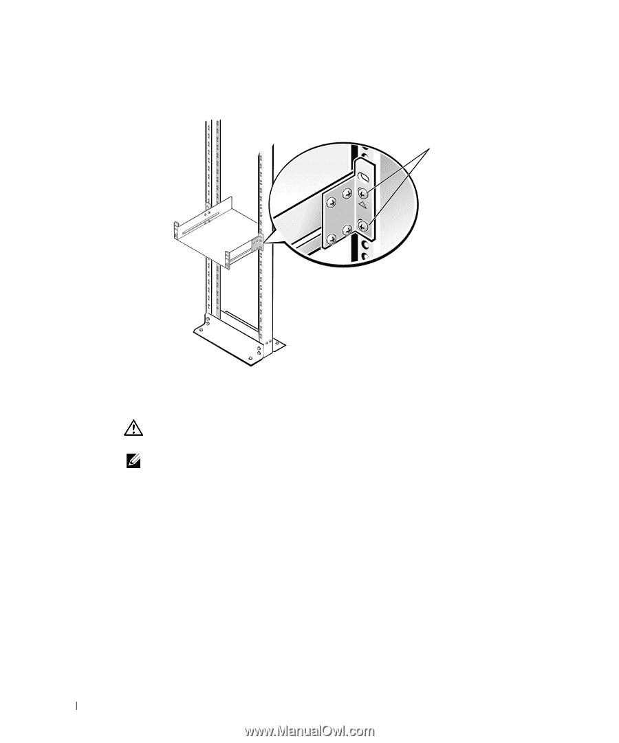
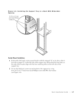
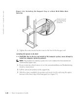
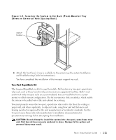
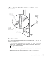
www.dell.com | support.dell.com Figure 1-8. Installing the Support Tray in a Rack With Wide-Hole Spacing 12-24 x 0.5-inch pan-head Phillip screws (4) 7 Tighten the center-mount bracket screws to the front of the two-post rack. Installing the System in the Rack CAUTION: Due to the size and weight of the computer system, never attempt to install the computer system by yourself. NOTE: The procedure for installing a system into a rack is identical for flush-mounted and center-mounted support trays. 1 If your system has a bezel, remove it (see the system Installation and Troubleshooting Guide for instructions). 2 Lift the system into position on the support tray. 3 Slide the system completely into position and secure it to the rack using the captive fasteners at the lower edge of the front panel (see Figure 1-9). 1-10 Rack Installation Guide
-
 1
1 -
2
-
3
-
4
-
5
-
6
-
7
-
8
-
9
-
10
-
 11
11 -
 12
12 -
 13
13 -
 14
14 -
 15
15 -
 16
16 -
 17
17 -
 18
18 -
 19
19 -
 20
20 -
 21
21 -
22
-
23
-
24
-
25
-
26
-
27
-
28
-
29
-
30
-
31
-
32
-
33
-
34
-
35
-
36
-
37
-
38
-
39
-
40
 |
 |