Dell PowerEdge 2900 Installing the Stabilizer Feet and/or the Optional
Dell PowerEdge 2900 Manual
 |
View all Dell PowerEdge 2900 manuals
Add to My Manuals
Save this manual to your list of manuals |
Dell PowerEdge 2900 manual content summary:
- Dell PowerEdge 2900 | Installing the Stabilizer Feet and/or the Optional
- Page 1
in the foot tab slots. See Figure 1. Repeat to install the remaining foot. Installing the Optional Casters NOTE: For an existing configuration, you must remove the stabilizer feet from the system before installing the casters. See "Removing the Stabilizer Feet" for instructions. 1 Slide the caster - Dell PowerEdge 2900 | Installing the Stabilizer Feet and/or the Optional
- Page 2
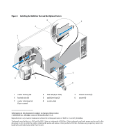
1 caster locking tab 4 foot tab slot (4) 7 caster retaining tab (3 per caster) 2 foot tab (2 per foot) 5 stabilizer foot (2) 8 caster plate 3 chassis cutout (4) 6 caster (4) Information in this document is subject to change without notice. © 2006 Dell Inc. All rights reserved. Printed in the - Dell PowerEdge 2900 | Installing the Stabilizer Feet and/or the Optional
- Page 3
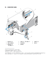
关于警告 1 45 千克(100 2 1-1 1 1-1 2 1-1 2006 年 2 月 - Dell PowerEdge 2900 | Installing the Stabilizer Feet and/or the Optional
- Page 4
图 1 3 4 2 1 5 8 7 6 1 4 4) 7 3 个) 2 2 个) 5 2) 8 3 4) 6 脚轮 (4) 2006 Dell Inc Dell Inc Dell 和 DELL 徽标是 Dell Inc Dell Inc - Dell PowerEdge 2900 | Installing the Stabilizer Feet and/or the Optional
- Page 5
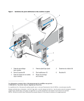
les roulettes en option, vous devez les fixer aux pieds stabilisateurs avant de fixer ces derniers au système. Pour plus d'instructions, voir "Installation des roulettes en option". Fixez un premier pied stabilisateur au système en alignant ses pattes avec les ouvertures du châssis qui se trouvent - Dell PowerEdge 2900 | Installing the Stabilizer Feet and/or the Optional
- Page 6
Figure 1. Installation des pieds stabilisateurs et des roulettes en option 3 4 2 1 5 8 7 6 1 Patte de (4) Les informations contenues dans ce document peuvent être modifiées sans préavis. © 2006 Dell Inc. Tous droits réservés. Imprimé aux États-Unis. La reproduction de ce document de - Dell PowerEdge 2900 | Installing the Stabilizer Feet and/or the Optional
- Page 7
. 2 Legen Sie das System auf eine ebene Arbeitsfläche, wobei die Unterseite des Systems über den Rand der Fläche hinausragt. Installation der Stabilisatoren ANMERKUNG: Wenn Sie die optionalen Laufrollen verwenden wollen, müssen Sie diese an den Stabilisatoren befestigen, bevor Sie die Stabilisatoren - Dell PowerEdge 2900 | Installing the Stabilizer Feet and/or the Optional
- Page 8
in den USA. Die Reproduktion dieses Dokuments in jeglicher Form ist ohne schriftliche Genehmigung von Dell Inc. streng untersagt. Marken in diesem Text: Dell und das DELL Logo sind Marken von Dell Inc. Andere in diesem Dokument möglicherweise verwendete Marken und Handelsnamen beziehen sich auf die - Dell PowerEdge 2900 | Installing the Stabilizer Feet and/or the Optional
- Page 9
1 45 kg 1 2 1 1 1 3 2 2 1 2006 年 2 月 - Dell PowerEdge 2900 | Installing the Stabilizer Feet and/or the Optional
- Page 10
図 1 3 4 2 1 5 8 7 6 1 4 4) 7 3 つ) 2 2 つ) 5 2) 8 3 4) 6 4) 2006 Dell Inc Printed in the U.S.A. Dell Inc Dell および DELL ロゴは Dell Inc Dell Inc - Dell PowerEdge 2900 | Installing the Stabilizer Feet and/or the Optional
- Page 11
1 45kg(100 2 1 1 1 2 1 2006 년 2 월 - Dell PowerEdge 2900 | Installing the Stabilizer Feet and/or the Optional
- Page 12
그림 1 3 4 2 1 5 8 7 6 1 4 4) 7 3 개 ) 2 2 개 ) 5 2) 8 3 4) 6 캐스터 (4) 2006 Dell Inc. All rights reserved Dell Inc Dell, DELL 로고는 Dell Inc Dell Inc - Dell PowerEdge 2900 | Installing the Stabilizer Feet and/or the Optional
- Page 13
situadas en el pie estabilizador. Vea la figura 1. Repita el mismo procedimiento para instalar las tres otras ruedas (dos por pie). 2 Instale los pies estabilizadores en el sistema. Consulte "Instalación de los pies estabilizadores". Desinstalación de los pies estabilizadores Para desinstalar un pie - Dell PowerEdge 2900 | Installing the Stabilizer Feet and/or the Optional
- Page 14
8 Placa de la rueda 3 Hendidura del chasis (4) 6 Rueda (4) La información contenida en este documento puede modificarse sin previo aviso. © 2006 Dell Inc. Reservados todos los derechos. Impreso en EE. UU. Queda estrictamente prohibida la reproducción de este documento en cualquier forma sin la
-
 1
1 -
 2
2 -
 3
3 -
 4
4 -
 5
5 -
 6
6 -
 7
7 -
8
-
9
-
10
-
11
-
12
-
13
-
14
 |
 |
About Cautions
CAUTION:
A CAUTION indicates a potential for property damage, personal injury, or death.
Installing the Stabilizer Feet and/or the Optional Casters
on Your System
This document provides instructions for installing the stabilizer feet and/or the optional casters
on your system. To prepare your system, perform the following steps:
1
Disconnect the system and any attached peripherals from their electrical outlets, and then
disconnect the peripherals from the system.
CAUTION:
The system may weigh up to 45 kilograms (100 pounds) when fully loaded. To prevent
personal injury, do not attempt to move the system by yourself.
2
Place the system on a flat work surface with the bottom of the system overhanging the surface
edge.
Installing the Stabilizer Feet
NOTE:
If you plan to install the optional casters, you must install the casters on the stabilizer feet before
installing the feet on your system. See "Installing the Optional Casters" for instructions.
To install the stabilizer foot on the system, align the foot tabs with the chassis cutouts on the
bottom of the system, and slide the tabs into the cutouts until the tabs lock into place in the
foot tab slots. See Figure 1. Repeat to install the remaining foot.
Installing the Optional Casters
NOTE:
For an existing configuration, you must remove the stabilizer feet from the system before
installing the casters. See "Removing the Stabilizer Feet" for instructions.
1
Slide the caster plate under the caster retaining tabs on the stabilizer foot until the caster
locking tab locks into place behind the caster. See Figure 1. Repeat to install the remaining
three casters, installing two casters per foot.
2
Install the stabilizer feet on your system. See "Installing the Stabilizer Feet."
Removing the Stabilizer Feet
To remove the stabilizer foot from the system, locate the foot tabs, which are locked in the foot
tab slots. Press down and hold both tabs, and then slide the foot away from the slots until the
tabs are free from the chassis. See Figure 1. Repeat to remove the remaining foot.
February 2006