Dell PowerEdge 2900 Installing the Stabilizer Feet and/or the Optional - Page 2
Installing the Stabilizer Feet and the Optional Casters, caster locking tab - documentation
 |
View all Dell PowerEdge 2900 manuals
Add to My Manuals
Save this manual to your list of manuals |
Page 2 highlights
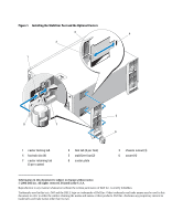
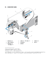
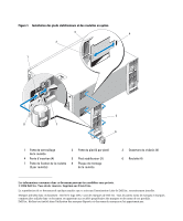
Figure 1. Installing the Stabilizer Feet and the Optional Casters 3 4 2 1 5 8 7 6 1 caster locking tab 4 foot tab slot (4) 7 caster retaining tab (3 per caster) 2 foot tab (2 per foot) 5 stabilizer foot (2) 8 caster plate 3 chassis cutout (4) 6 caster (4) Information in this document is subject to change without notice. © 2006 Dell Inc. All rights reserved. Printed in the U.S.A. Reproduction in any manner whatsoever without the written permission of Dell Inc. is strictly forbidden. Trademarks used in this text: Dell and the DELL logo are trademarks of Dell Inc. Other trademarks and trade names may be used in this document to refer to either the entities claiming the marks and names or their products. Dell Inc. disclaims any proprietary interest in trademarks and trade names other than its own.
-
 1
1 -
 2
2 -
 3
3 -
 4
4 -
 5
5 -
 6
6 -
 7
7 -
 8
8 -
9
-
10
-
11
-
12
-
13
-
14
 |
 |
