Dell PowerEdge 4100 Service Manual
Dell PowerEdge 4100 Manual
 |
View all Dell PowerEdge 4100 manuals
Add to My Manuals
Save this manual to your list of manuals |
Dell PowerEdge 4100 manual content summary:
- Dell PowerEdge 4100 | Service Manual - Page 1
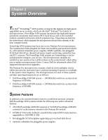
Dell® PowerEdge® 4100/180 and 4100/200 Systems SERVICE MANUAL ® - Dell PowerEdge 4100 | Service Manual - Page 2
. Reproduction in any manner whatsoever without the written permission of Dell Computer Corporation is strictly forbidden. Trademarks used in this text: Dell, the DELL logo, and PowerEdge are registered trademarks of Dell Computer Corporation; Intel, Pentium, and LANDesk are registered trademarks of - Dell PowerEdge 4100 | Service Manual - Page 3
serviceability and increased reliability, with optional redundant power supplies, RAID capability, hot-pluggable SCSI hard-disk drives, thermal and power supply monitoring, redundant fans, and ECC memory. The PowerEdge 4100 systems are freestanding or can be rackmounted to integrate your servers - Dell PowerEdge 4100 | Service Manual - Page 4
system features, see "Technical Specifications" found later in this chapter. For information about installing the PowerEdge 4100 systems in a rack, see the "Dell PowerEdge 4100 and 6100 Systems Rack Kit Installation Guide" (P/N 40722). 1-2 Dell PowerEdge 4100/180 and 4100/200 Systems Service Manual - Dell PowerEdge 4100 | Service Manual - Page 5
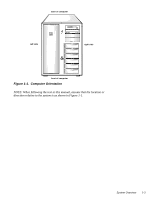
back of computer left side right side front of computer Figure 1-1. Computer Orientation NOTE: When following the text in this manual, assume that the location or direction relative to the system is as shown in Figure 1-1. System Overview 1-3 - Dell PowerEdge 4100 | Service Manual - Page 6
power button and power-on indicator diskette-drive access indicator (typical) SCSI hard-disk drive online indicator SCSI hard-disk drive fault indicator Figure 1-2. Front-Panel Features SCSI rebooted by pressing . 1-4 Dell PowerEdge 4100/180 and 4100/200 Systems Service Manual - Dell PowerEdge 4100 | Service Manual - Page 7
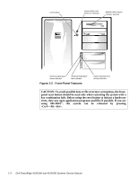
expansion slots system board microprocessor sockets cooling fan connectors (3) (cooling fans are located behind the air intake panel) Figure 1-3. Front/Left Internal View external drive bays (4) control panel internal drive bays (6) hard-disk drive security lock air intake panel System Overview - Dell PowerEdge 4100 | Service Manual - Page 8
) internal drive bays (6) SCSI backplane board SCSI power connector server management connector control panel connector power supply (optional) power supply SMB connector Figure 1-4. Back/Right Internal View SCSI connector port 1-6 Dell PowerEdge 4100/180 and 4100/200 Systems Service Manual - Dell PowerEdge 4100 | Service Manual - Page 9
cable strain relief power supply red LED green LED AC power receptacle SMB connector Figure 1-5. I/O Panel video connector server-management serial port connector parallel port connector serial port 2 connector serial port 1 connector mouse connector keyboard connector SCSI connector port - Dell PowerEdge 4100 | Service Manual - Page 10
in the Dell PowerEdge 4100/180 and 4100/200 Systems User's Guide describes the EISA Configuration Utility and provides instructions for server management circuitry works in conjunction with the Intel LANDesk® Server Management suite. 1-8 Dell PowerEdge 4100/180 and 4100/200 Systems Service Manual - Dell PowerEdge 4100 | Service Manual - Page 11
DRAM memory (the video memory Dell PowerEdge 4100/180 and 4100/200 Systems Installation and Troubleshooting Guide. For detailed information about installing SCSI hard-disk drives, see Chapter 10, "Installing Drives in the Internal Bays," in the Installation and Troubleshooting Guide. Dell supports - Dell PowerEdge 4100 | Service Manual - Page 12
last device on the SCSI cable. Therefore, any additional devices attached to the cable should have their terminators disabled. See the documentation provided with the SCSI device for information on disabling the device's terminator. 1-10 Dell PowerEdge 4100/180 and 4100/200 Systems Service Manual - Dell PowerEdge 4100 | Service Manual - Page 13
service-related information about the system unit. System Power Supply The 500-W system power supply can operate from an AC power source of 90 to 265 VAC at 50 or 60 Hz. When the power-supply paralleling board is installed, the power supplies are hot-pluggable. When the red LED on the power supply - Dell PowerEdge 4100 | Service Manual - Page 14
connector panel (J11, J12, J13, J14, and J15). The following illustrations show both sets of connectors. P2 P1 P5 P4 P3 Figure 1-6. Power Supply Connectors J12 (P2) J11 (P1) J15 (P5) J14 (P4) J13 (P3) Figure 1-7. Power Connector Panel 1-12 Dell PowerEdge 4100/180 and 4100/200 Systems Service Manual - Dell PowerEdge 4100 | Service Manual - Page 15
between +4 and +5 VDC except when the power button on the front panel is pressed, taking PSON# to its active-low state. 2 Pin 5 - PWRGOOD should measure between +4 and +5 VDC when the power supply is on and operating to indicate that all power-supply output voltages are within the ranges specified - Dell PowerEdge 4100 | Service Manual - Page 16
red) +3.3 VDC (orange) +12 VDC (yellow) +3.3 VDC (orange) +5 VDC (red) Figure 1-9. DC Power Connectors J12 (P2), J13 (P3), and J14 (P4) J15 (P5) +SW1 +12 VDC (red) ) +FAN_TACH (gray) +SW1 Figure 1-10. DC Power Connector J15 (P5) 1-14 Dell PowerEdge 4100/180 and 4100/200 Systems Service Manual - Dell PowerEdge 4100 | Service Manual - Page 17
Figures 1-11 provides information about DC power distribution for the nonredundant PowerEdge 4100 system. P1-5 power supply # 1 PSON# +5 VFP +5 VDC +5 VDC power connector panel NOTE: A server management cable (16-pin) carries the +5 VFP from the system board to the SCSI backplane. The control - Dell PowerEdge 4100 | Service Manual - Page 18
for redundant systems can be measured at the connectors on the power-supply paralleling board (PWR1, PWR2, PWR3, PWRSCSI, and PWRFD) ) PWR2 diagnostics port PWR3 PWRSCSI (DDBP) Figure 1-12. Power-Supply Paralleling Board Connectors 1-16 Dell PowerEdge 4100/180 and 4100/200 Systems Service Manual - Dell PowerEdge 4100 | Service Manual - Page 19
12 13 14 15 16 17 18 PWR1 1 23 4 5 6 7 8 9 -12 VDC (blue) -5 VDC (white) PWR_STAT_BIT (gray) I 2C_SDA (gray) I 2C_SCL (gray) Figure 1-13. DC Power Connector PWR1 BAT_V (gray) PRES_DET (gray) NC_+12 sense +5 VDC sense (red) +3.3 VDC (orange) common (black) +12 VDC (yellow) common (black) +12 VDC - Dell PowerEdge 4100 | Service Manual - Page 20
VDC (red) 567 +12 VDC (yellow) +5 VDC (red) +12 VDC (yellow) Figure 1-15. DC Power Connector PWRSCSI (DDBP) +12 VDC (yellow) common (black) common (black) +5 VDC (red) PWRFD (FD1- Figure 1-16. DC Power Connector PWRFD (FD1-FD4) 1-18 Dell PowerEdge 4100/180 and 4100/200 Systems Service Manual - Dell PowerEdge 4100 | Service Manual - Page 21
Distribution (Redundant System) Figures 1-17 provides information about DC power distribution for the redundant PowerEdge 4100 system. power supply # 1 P1-5 POK PSON# +5 VFP +5 VDC -5 VDC +12 VDC -12 VDC +3.3 VDC P1-5 power supply # 2 PSON# +5 VFP +5 VDC -5 VDC +12 VDC -12 VDC +3.3 VDC PWR1 - Dell PowerEdge 4100 | Service Manual - Page 22
configuration jumpers primary microprocessor socket (PROCESSOR1) power supply connector (POWER3) secondary microprocessor server-management bus socket (PROCESSOR2) connector (SMB BACKPLANE) Figure 1-18. System Board Components 1-20 Dell PowerEdge 4100/180 and 4100/200 Systems Service Manual - Dell PowerEdge 4100 | Service Manual - Page 23
The eight DIMM sockets on the system board can accommodate combinations of 32- and 128-MB DIMMs up to a total memory capacity of 1024 MB (1 GB). The system is shipped with high-speed (60-ns) 3.3-V EDO DIMMs installed. When reinstalling DIMMs, use the following guidelines: • Install a - Dell PowerEdge 4100 | Service Manual - Page 24
drive requires service IRQ7 Generated by super I/O controller to indicate that device connected to parallel port requires service IRQ8 Generated by keyboard controller for each tick of RTC IRQ9 Available for use by expansion card 1-22 Dell PowerEdge 4100/180 and 4100/200 Systems Service Manual - Dell PowerEdge 4100 | Service Manual - Page 25
Table 1-3. Interrupt Assignments (continued) IRQ Line Used/Available IRQ10 Available for use by expansion card IRQ11 Available for use by expansion card IRQ12 Generated by keyboard controller to indicate that mouse's output buffer is full IRQ13 Generated by math coprocessor to indicate coprocessor - Dell PowerEdge 4100 | Service Manual - Page 26
expansion-card connector data width (maximum 32 bits PCI expansion-card connector size 120 pins PCI expansion-card connector data width (maximum 32 bits 1-24 Dell PowerEdge 4100/180 and 4100/200 Systems Service Manual - Dell PowerEdge 4100 | Service Manual - Page 27
Specifications (continued) System Clocks System clock 60 or 66 MHz (matches external processor bus speed) Diskette/communications ports 24 MHz from the system clock Memory six 1- to 1.6-inch-high SCSI hard-disk drives, hot-pluggable with an optional PowerEdge Expandable RAID Controller host adapter - Dell PowerEdge 4100 | Service Manual - Page 28
and Indicators Reset control push button Power control push button Power indicator green LED Diskette drive access indicator green LED CD-ROM busy indicator . . . . green LED SCSI hard-disk drive online indicator green LED 1-26 Dell PowerEdge 4100/180 and 4100/200 Systems Service Manual - Dell PowerEdge 4100 | Service Manual - Page 29
Table 1-5. Technical Specifications (continued) Controls and Indicators (continued) SCSI hard-disk drive activity indicator green LED SCSI hard-disk drive fault indicator yellow LED Power-supply 5-VDC online indicator green LED Power-supply failure indicator red LED (flashes at power-on; stays - Dell PowerEdge 4100 | Service Manual - Page 30
Table 1-5. Technical Specifications (continued) Environmental (continued) Altitude: Operating 16 to 3048 m (-50 to 10,000 ft) Storage 16 to 10,600 m (-50 to 35,000 ft) z 1-28 Dell PowerEdge 4100/180 and 4100/200 Systems Service Manual - Dell PowerEdge 4100 | Service Manual - Page 31
are presented in this manual. Initial User Contact When you first contact a user who has a problem, ask the user to describe the problem and the conditions under which it occurs. A verbal description can often indicate the cause of a problem or else the appropriate troubleshooting procedure to use - Dell PowerEdge 4100 | Service Manual - Page 32
devices for any signs of physical damage. Does the inspection reveal any problems? Yes. Proceed to the appropriate procedure in Chapter 4, "Removing and Replacing Parts." No. Proceed to the next section, "Observing the Boot Routine." 2-2 Dell PowerEdge 4100/180 and 4100/200 Systems Service Manual - Dell PowerEdge 4100 | Service Manual - Page 33
. To observe problem indications during the boot routine, follow these steps: 1. If the system is off, turn on all peripherals and the computer. Insert the Dell Server Assistant CD into the CD-ROM drive. Press the reset button or to reboot the system. 2. Check the power supply fans - Dell PowerEdge 4100 | Service Manual - Page 34
Dell Server lead to the source of a problem, such as a loose expansion , each power supply bay must have either a power supply or the power closeout panel an expansion card, use a 1/4-inch nut driver to remove the screw that secures the card- Dell PowerEdge 4100/180 and 4100/200 Systems Service Manual - Dell PowerEdge 4100 | Service Manual - Page 35
power sources, and turn them on. Does the problem appear Dell Server Assistant loads, a program tests the portion of main memory (RAM) required for loading the diagnostics. If a main memory error is detected, a message telling you which DIMM has failed appears on the screen. Basic Troubleshooting - Dell PowerEdge 4100 | Service Manual - Page 36
of the problem or leads to the proper troubleshooting steps for determining the source of the problem, call Dell for technical assistance. For instructions, see Chapter 11, "Getting Help," in the Installation and Troubleshooting Guide. 2-6 Dell PowerEdge 4100/180 and 4100/200 Systems Service Manual - Dell PowerEdge 4100 | Service Manual - Page 37
find it in Table 3-1. If the table does not lead to the source of the problem, run the appropriate tests in the CD-based diagnostics to assist in troubleshooting the problem. Beep Code 1-2 1-2-2-3 1-3-1-1 1-3-1-3 Table 3-1. Beep Codes Error Probable Causes Invalid expansion-card ROM checksum - Dell PowerEdge 4100 | Service Manual - Page 38
board. Reseat DIMMs or replace system board. CMOS failure Defective system board. Memory controller or DIMM failure Defective DIMMs or system board. Reseat DIMMs or DIMMs or system board. Reseat DIMMs or replace system board. 3-2 Dell PowerEdge 4100/180 and 4100/200 Systems Service Manual - Dell PowerEdge 4100 | Service Manual - Page 39
Error Messages Table 3-2 lists system error messages that can appear on the monitor screen. These messages can help you find the source of a problem. Some of these error messages indicate fatal errors. When a fatal error occurs, the system cannot usually be rebooted until an appropriate hardware - Dell PowerEdge 4100 | Service Manual - Page 40
. Defective system board. System memory size has changed Run Configuration Utility DIMM was added or removed. DIMMs are improperly seated. More memory was added. Make sure DIMMs are properly seated; run EISA Configuration Utility. 3-4 Dell PowerEdge 4100/180 and 4100/200 Systems Service Manual - Dell PowerEdge 4100 | Service Manual - Page 41
. Nonidentical CPUs - System halted. Cache memory sizes of the two Pentium Pro microprocessors 180 MHz or 200 MHz. Check microprocessor speed jumpers. Power supply paralleling board firmware download failed System backplane firmware download failed Server-management bus cable connection to SCSI - Dell PowerEdge 4100 | Service Manual - Page 42
3-6 Dell PowerEdge 4100/180 and 4100/200 Systems Service Manual - Dell PowerEdge 4100 | Service Manual - Page 43
the steps in "Precautionary Measures" found later in this chapter. • You have removed the computer covers. • You can replace or reinstall a part by performing the removal procedure in reverse order unless additional information is provided. Recommended Tools Most of the procedures in this chapter - Dell PowerEdge 4100 | Service Manual - Page 44
power sources to reduce the potential for personal injury. 3. Disconnect any communications cables. 4. Wear a wrist grounding strap, and clip it to an unpainted metal sur- face, such as a part (6) Figure 4-1. Computer Covers Removal 4-2 Dell PowerEdge 4100/180 and 4100/200 Systems Service Manual - Dell PowerEdge 4100 | Service Manual - Page 45
panel of the computer to the unlocked position (see Figure 4-2). keylock (2) Figure 4-2. Keylocks on Computer's Back Panel 2. Loosen the three screws along the back edge of the cover (see Figure 4-1). 3. Slide the cover toward the back of the computer an inch or so. Then grasp the top of the cover - Dell PowerEdge 4100 | Service Manual - Page 46
steps: 1. Remove the computer covers. 2. Release the two tabs on each side of the bezel. 3. Slide the front bezel toward the front of the computer. 4-4 Dell PowerEdge 4100/180 and 4100/200 Systems Service Manual - Dell PowerEdge 4100 | Service Manual - Page 47
the following subsections. DC power cable diskette/tape drive interface cable 3.5-inch SCSI connector (SCSI2 CD-ROM) SCSI connector (BACKPLANE SCSI1) Figure 4-4. Drive Hardware system board SCSI hard-disk drive bay (6) SCSI backplane board SCSI interface cable Removing and Replacing Parts - Dell PowerEdge 4100 | Service Manual - Page 48
and carefully press the insert into place. A tab on each side of the insert snaps into a corresponding latch on the inside of the front bezel. 4-6 Dell PowerEdge 4100/180 and 4100/200 Systems Service Manual - Dell PowerEdge 4100 | Service Manual - Page 49
assembly from one of the externally accessible drive bays, follow these steps: 1. Disconnect the DC power cable and the interface cable from the back of the drive. Be sure to record the power connector number and interface cable connector identification. 2. Press inward (toward center of drive) on - Dell PowerEdge 4100 | Service Manual - Page 50
of the old drive for an adapter. If present, remove the adapter and retain it for use on the new drive. When reinstalling the SCSI drive, set the SCSI address jumpers and the SCSI bus termination jumpers to the settings you recorded. 4-8 Dell PowerEdge 4100/180 and 4100/200 Systems Service Manual - Dell PowerEdge 4100 | Service Manual - Page 51
adapter card is installed. 1. If a PowerEdge Expandable RAID Controller host adapter card is installed in the computer, wait until the three indicators are off, and then proceed to Step 2 (refer to Chapter 6, "Installing SCSI Hard-Disk Drives," in the User's Guide for more information). If this host - Dell PowerEdge 4100 | Service Manual - Page 52
in the bay, turn on the system. The online indicator (green) lights, indicating power is being supplied to the hard-disk drive. With the controller connected, the activity LED is activated when the controller spins up the drive. 4-10 Dell PowerEdge 4100/180 and 4100/200 Systems Service Manual - Dell PowerEdge 4100 | Service Manual - Page 53
ten hooks holding the board to the computer chassis, and lift the board away from the computer. An insulator (similar to the one for the power-supply paralleling board in Figure 4-12) is attached to the back of the SCSI backplane board with two adhesive strips. Removing and Replacing Parts 4-11 - Dell PowerEdge 4100 | Service Manual - Page 54
the other end of the cable from the power supply. 4. Turn the insertion screw counterclockwise to release the power supply. 5. Slide the power supply out of the chassis. To replace a power supply, perform these steps in reverse order. 4-12 Dell PowerEdge 4100/180 and 4100/200 Systems Service Manual - Dell PowerEdge 4100 | Service Manual - Page 55
back of the computer approximately 1 inch. 2. Disconnect all cables from the power-supply paralleling board. 3. Unscrew the thumb screw. 4. Disengage the board from the eleven hooks holding it to the computer chassis, and then lift the board away from the computer. Removing and Replacing Parts 4-13 - Dell PowerEdge 4100 | Service Manual - Page 56
cables (from the system board, the SCSI backplane board, and so forth). 3. Unscrew the retainer screw. 4. Disengage the panel from the four hooks holding it to the computer chassis, and then lift the panel away from the computer. 4-14 Dell PowerEdge 4100/180 and 4100/200 Systems Service Manual - Dell PowerEdge 4100 | Service Manual - Page 57
. 3. Disengage the panel from the four hooks holding the panel to the computer chassis, and lift the panel away from the computer. Removing and Replacing Parts 4-15 - Dell PowerEdge 4100 | Service Manual - Page 58
procedure can be performed with the computer turned on. The middle fan is normally turned off by server management; this fan is turned on only if one of the other fans fails. 1. Remove the two fan retention tabs inside the carrier. 4-16 Dell PowerEdge 4100/180 and 4100/200 Systems Service Manual - Dell PowerEdge 4100 | Service Manual - Page 59
Board Components Ultra/Wide SCSI host adapter connector (BACKPLANE SCSI1) power supply connector (POWER2) power supply connector (POWER1) primary microprocessor socket (PROCESSOR1) power supply connector (POWER3) server-management bus connector (SMB BACKPLANE) Removing and Replacing Parts 4-17 - Dell PowerEdge 4100 | Service Manual - Page 60
from the card-mounting bracket. 4. If the card is a full-length expansion card, unlock the locking cam on the locking card guide. 5. Grasp the expansion card by its corners, and carefully remove it from the expansion-card connector. 4-18 Dell PowerEdge 4100/180 and 4100/200 Systems Service Manual - Dell PowerEdge 4100 | Service Manual - Page 61
press the DIMM straight down into the socket slot until the securing clips snap into place around both ends of the DIMM. Removing and Replacing Parts 4-19 - Dell PowerEdge 4100 | Service Manual - Page 62
can get extremely hot during system operations. Be sure the chip has had sufficient time to cool before touching it. Press down on the folded part of the clip with a small screwdriver to release the clip (see Figure 4-21). 4-20 Dell PowerEdge 4100/180 and 4100/200 Systems Service Manual - Dell PowerEdge 4100 | Service Manual - Page 63
from its socket. Bending the pins can permanently damage the microprocessor chip. microprocessor chip microprocessor socket release lever Figure 4-22. Removing a Microprocessor Removing and Replacing Parts 4-21 - Dell PowerEdge 4100 | Service Manual - Page 64
sink, place the thermal interface pad that comes with the replacement microprocessor between the microprocessor and the heat sink before reinstalling the securing clip. 4-22 Dell PowerEdge 4100/180 and 4100/200 Systems Service Manual - Dell PowerEdge 4100 | Service Manual - Page 65
steps. WARNING: The new battery can explode if installed incorrectly. Be careful to replace the battery as instructed in the following procedure. In addition, replace the old battery only with one of the same or information that was lost while replacing the battery. Removing and Replacing Parts 4-23 - Dell PowerEdge 4100 | Service Manual - Page 66
replacing a system board, remove the DIMMs, the microprocessor(s), and the expansion card from the old system board and install them on the replacement board. 4-24 Dell PowerEdge 4100/180 and 4100/200 Systems Service Manual - Dell PowerEdge 4100 | Service Manual - Page 67
, press during the power-on self-test (POST). If you wait too long, the operating system begins to load into memory and you cannot enter the System settings or information (right column) • Help box - Displays item-specific help for the category whose field is cur- rently highlighted • Key - Dell PowerEdge 4100 | Service Manual - Page 68
Setup values for all menus Loads previously stored configuration values for the current menu Executes a command or selects a submenu Refreshes the screen A-2 Dell PowerEdge 4100/180 and 4100/200 Systems Service Manual - Dell PowerEdge 4100 | Service Manual - Page 69
help box title box Dell System PowerEdge 4100/200 Setup Main Advanced Memory Cache: [Enable] Boot Sequence: [A: then C:] Num Lock: [On] Speaker: [On] BIOS Version AXX Item Specific 200 Pentium Pro 200 512 KB Base Memory: 640 KB Extended Memory: 63 MB Video Memory: 1 MB Service - Dell PowerEdge 4100 | Service Manual - Page 70
. Video Memory Displays amount of video memory installed on the system board. Service Tag Displays system's five-character service tag number. Asset Tag Displays the asset tag number, up to ten characters, if one is assigned. A-4 Dell PowerEdge 4100/180 and 4100/200 Systems Service Manual - Dell PowerEdge 4100 | Service Manual - Page 71
Dell System PowerEdge 4100/200 Setup Main Advanced Security Exit Boot Options Boot Sequence: [A: then C:] Setup Prompt: [Enabled] POST Errors: [Enabled] Diskette Drive Check: [Enabled] Reset Button: [Enabled] BIOS Version AXX Item Specific boot program after power-on Setup Prompt Enables - Dell PowerEdge 4100 | Service Manual - Page 72
] BIOS Version AXX Item Specific Help Configures the system's built-in serial port. F1 Help ESC Exit Select Item Select Menu -/+ Change Values Enter Select Sub-Menu Figure A-3. Advanced Menu F9 Setup Defaults F10 Previous Values A-6 Dell PowerEdge 4100/180 and 4100/200 Systems Service Manual - Dell PowerEdge 4100 | Service Manual - Page 73
the built-in SCSI 7860 Ultra/Narrow controller and determines if it is scanned as a boot drive. PCI Scan Sequence Determines the sequence the PCI devices are scanned to find a boot device (default is Embedded devices first). Use MP Specification Determines the microprocessorspecification - Dell PowerEdge 4100 | Service Manual - Page 74
] Virus Check Reminder [Disabled] BIOS Version AXX Item Specific Help F1 Help ESC Exit Select Item Select Menu -/+ Change Values Enter Select Sub-Menu F9 Setup Defaults F10 Previous Values Figure A-4. Security Menu A-8 Dell PowerEdge 4100/180 and 4100/200 Systems Service Manual - Dell PowerEdge 4100 | Service Manual - Page 75
dialog box for entering a new user password (up to seven alphanumeric characters). See "Using the User Password Feature" in Chapter 4 of the User's Guide. Password on Boot Allows you to require the entry of a supervisor password before the boot process of the system can be completed. Requires use - Dell PowerEdge 4100 | Service Manual - Page 76
Dell System PowerEdge 4100/200 Setup Main Advanced Security Exit Save Changes & Exit Exit Without Saving Changes Get Default Values Load Previous Values Save Changes BIOS Version AXX Item Specific F9 Setup Defaults F10 Previous Values A-10 Dell PowerEdge 4100/180 and 4100/200 Systems Service Manual - Dell PowerEdge 4100 | Service Manual - Page 77
Table A-6. Exit Menu Categories Category Function Save Changes and Exit Saves the changes you have made before you exit the System Setup program. The next time you boot up, the BIOS configures your system according to the selections stored in CMOS. Exit Without Saving Changes Exits the System - Dell PowerEdge 4100 | Service Manual - Page 78
A-12 Dell PowerEdge 4100/180 and 4100/200 Systems Service Manual - Dell PowerEdge 4100 | Service Manual - Page 79
DC power, 1-12 card-slot opening, 4-18 carrier, hard-disk drive removal, 4-9 CD-ROM drive illustrated, 4-5 removal, 4-7 computer back/right side internal view, 1-6 front/left internal view, 1-5 orientation, 1-3 technical specifications, 1-24 configuration guidelines SCSI drives, 1-9 configuration - Dell PowerEdge 4100 | Service Manual - Page 80
server management, 1-8 video controller, 1-9 interrupt assignments list of, 1-22 ISA expansion cards, 4-18 J jumpers list of, 1-22 K KEYBOARD connector, 4-17 keyboard connector location on I/O panel, 1-7 location on system board, 4-17 2 Dell PowerEdge 4100/180 and 4100/200 Systems Service Manual - Dell PowerEdge 4100 | Service Manual - Page 81
memory main 4-17 POWER2 connector, 4-17 power-supply paralleling board connector configuration, 1-16 SCSI BACKPLANE connector, 4-17 SCSI CD-ROM connector, 4-17 SCSI connectors, 4-17 SCSI controllers, integrated, 1-9 SCSI devices ID numbers, 1-10 SCSI hard-disk drives. See hard-disk drives, SCSI SCSI - Dell PowerEdge 4100 | Service Manual - Page 82
, 4-17 Ultra/Wide SCSI host adapter connector, 4- 17 user contact, initial, 2-1 V video connector location on I/O panel, 1-7 location on system board, 4-17 video controller, integrated, 1-9 visual inspection external, 2-2 internal, 2-4 4 Dell PowerEdge 4100/180 and 4100/200 Systems Service Manual
-
 1
1 -
 2
2 -
 3
3 -
 4
4 -
 5
5 -
 6
6 -
 7
7 -
8
-
9
-
10
-
11
-
12
-
13
-
14
-
15
-
16
-
17
-
18
-
19
-
20
-
21
-
22
-
23
-
24
-
25
-
26
-
27
-
28
-
29
-
30
-
31
-
32
-
33
-
34
-
35
-
36
-
37
-
38
-
39
-
40
-
41
-
42
-
43
-
44
-
45
-
46
-
47
-
48
-
49
-
50
-
51
-
52
-
53
-
54
-
55
-
56
-
57
-
58
-
59
-
60
-
61
-
62
-
63
-
64
-
65
-
66
-
67
-
68
-
69
-
70
-
71
-
72
-
73
-
74
-
75
-
76
-
77
-
78
-
79
-
80
-
81
-
82
 |
 |

Dell
®
PowerEdge
®
4100/180 and 4100/200 Systems
SERVICE MANUAL
®