Dell PowerEdge 4100 Service Manual - Page 81
SCSI BACKPLANE connector
 |
View all Dell PowerEdge 4100 manuals
Add to My Manuals
Save this manual to your list of manuals |
Page 81 highlights
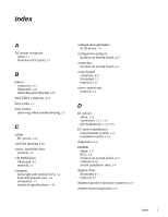
M memory main, 1-21 system, 1-8 messages, error, 3-3 microprocessor release lever, 4-21 removal, 4-20, 4-21 sockets, 4-17 microprocessor cooling fans removal, 4-16 MONITOR connector, 4-17 MOUSE connector, 4-17 mouse connector location on I/O panel, 1-7 location on system board, 4-17 P padlock, 4-3 PARALLEL connector, 4-17 parallel port connector location on I/O panel, 1-7 location on the system board, 4-17 PCI expansion cards, 1-8, 4-18 PCI expansion-card connectors, 4-17 Plug and Play ISA expansion cards, 1-8 POST beep codes, 3-1 power AC power receptacle, 1-7 indicator, 1-4 switch, 1-4 power connector plate removal, 4-14 power distribution diagram nonredundant system, 1-15 redundant system, 1-19 power supply about, 1-11 connector configuration, 1-12 connectors, 4-17 DC voltage ranges, 1-11 illustrated, 1-12 removal, 4-12 voltage output ranges, 1-11 POWER1 connector, 4-17 POWER2 connector, 4-17 power-supply paralleling board connector configuration, 1-16 illustrated, 1-16 removal, 4-13 precautions, 4-2 PROCESSOR1 connector, 4-17 PROCESSOR2 connector, 4-17 R REMOTE connector, 4-17 reset button location on I/O panel, 1-4 resource conflicts eliminating, 2-5 S SCSI BACKPLANE connector, 4-17 SCSI CD-ROM connector, 4-17 SCSI connectors, 4-17 SCSI controllers, integrated, 1-9 SCSI devices ID numbers, 1-10 SCSI hard-disk drives. See hard-disk drives, SCSI SCSI ID numbers, 1-10 SERIAL connectors, 4-17 Index 3
-
 1
1 -
2
-
3
-
4
-
5
-
6
-
7
-
8
-
9
-
10
-
11
-
12
-
13
-
14
-
15
-
16
-
17
-
18
-
19
-
20
-
21
-
22
-
23
-
24
-
25
-
26
-
27
-
28
-
29
-
30
-
31
-
32
-
33
-
34
-
35
-
36
-
37
-
38
-
39
-
40
-
41
-
42
-
43
-
44
-
45
-
46
-
47
-
48
-
49
-
50
-
51
-
52
-
53
-
54
-
55
-
56
-
57
-
58
-
59
-
60
-
61
-
62
-
63
-
64
-
65
-
66
-
67
-
68
-
69
-
70
-
71
-
72
-
73
-
74
-
75
-
 76
76 -
 77
77 -
 78
78 -
 79
79 -
 80
80 -
 81
81 -
 82
82
 |
 |
