Dell Precision M20 Dell Precision M20 Service Manual
Dell Precision M20 Manual
 |
View all Dell Precision M20 manuals
Add to My Manuals
Save this manual to your list of manuals |
Dell Precision M20 manual content summary:
- Dell Precision M20 | Dell Precision M20 Service Manual - Page 1
Dell Precision™ M20 Service Manual Before You Begin System Components Hard Drive Memory Module, Modem, and Devices Coin-Cell Battery Mini PCI Card Internal Card With Bluetooth® Wireless Technology Center Control Cover Keyboard Display Assembly and Display Latch Palm Rest Fan Microprocessor Thermal - Dell Precision M20 | Dell Precision M20 Service Manual - Page 2
Back to Contents Page Before You Begin Dell Precision™ M20 Service Manual Preparing to Work Inside the Computer Recommended Tools Computer Orientation Screw Identification Preparing to Work Inside the Computer CAUTION: Only a certified service technician should perform repairs on your computer. - Dell Precision M20 | Dell Precision M20 Service Manual - Page 3
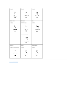
12. Remove the hard drive. Recommended Tools The procedures in this manual require the following tools: l #1 Phillips screwdriver l ¼-inch flat-blade screwdriver l Small plastic scribe l Flash BIOS update program floppy or CD Computer Orientation 1 back 2 right 3 front 4 left Screw - Dell Precision M20 | Dell Precision M20 Service Manual - Page 4
(4 each) (6 each) (4 each) Display Latch: (1 each) Palm Rest: (2 each at top) Fan: (2 each) (13 each at bottom) Speakers: (2 each-1 on each side) Modem: (1 each) System Board: (5 each) Back to Contents Page - Dell Precision M20 | Dell Precision M20 Service Manual - Page 5
BIOS Dell Precision™ M20 Service Manual 1. Ensure that the AC adapter is plugged in and that the main battery is installed properly. NOTE: If you use a BIOS update program CD to flash the BIOS, set up the computer to boot from a CD before inserting the CD. 2. Insert the BIOS update program floppy - Dell Precision M20 | Dell Precision M20 Service Manual - Page 6
® Wireless Technology Dell Precision™ M20 Service Manual Removing the Internal Card With Bluetooth® Wireless Technology Installing the Internal Card With Bluetooth® Wireless Technology CAUTION: Before performing the following procedures, read the safety instructions in your Product Information Guide - Dell Precision M20 | Dell Precision M20 Service Manual - Page 7
Back to Contents Page - Dell Precision M20 | Dell Precision M20 Service Manual - Page 8
to Contents Page Coin-Cell Battery Dell Precision™ M20 Service Manual Removing the Coin-Cell Battery Installing the Coin-Cell Battery CAUTION: Before you begin any of the procedures in this section, follow the safety instructions located in the Product Information Guide. CAUTION: To prevent static - Dell Precision M20 | Dell Precision M20 Service Manual - Page 9
connector 4 securing sleeve Installing the Coin-Cell Battery 1. Connect the coin-cell battery cable connector to the battery connector on the system board. 2. Slide the battery into the securing sleeve. 3. Replace the modem cover. Back to Contents Page - Dell Precision M20 | Dell Precision M20 Service Manual - Page 10
Module Dell Precision™ M20 Service Manual Removing the Microprocessor Module Installing the Microprocessor Module Removing the Microprocessor Module CAUTION: Before you begin any of the procedures in this section, follow the safety instructions located in the Product Information Guide. NOTICE - Dell Precision M20 | Dell Precision M20 Service Manual - Page 11
the screw any further to secure the microprocessor module to the system board. 3. Replace the other computer parts you removed earlier in this procedure. 4. Update the BIOS using a flash BIOS update program CD. For instructions on how to flash the BIOS, see "Flashing the BIOS." Back to Contents Page - Dell Precision M20 | Dell Precision M20 Service Manual - Page 12
Display Assembly and Display Latch Dell Precision™ M20 Service Manual Display Assembly Display Bezel Display Panel Display Latch Display Assembly CAUTION: Before you begin any of the procedures in this section, follow the safety instructions located in the Product Information Guide. NOTICE: To avoid - Dell Precision M20 | Dell Precision M20 Service Manual - Page 13
an unpainted metal surface (such as the back panel) on the computer. Removing the Display Bezel 1. Follow the instructions in "Preparing to Work Inside the Computer." 2. Remove the center control cover. 3. Remove the keyboard. 4. Remove the display assembly. 5. Use a plastic scribe to pry the six - Dell Precision M20 | Dell Precision M20 Service Manual - Page 14
the bezel. 7. Starting at the bottom of the display panel (by the Dell™ logo), use your fingers to separate the bezel from the top cover by lifting procedures in this section, follow the safety instructions located in the Product Information Guide. NOTICE: To avoid electrostatic discharge, ground - Dell Precision M20 | Dell Precision M20 Service Manual - Page 15
the Display Panel 1. Follow the instructions in "Preparing to Work Inside the Computer." 2. Remove the center control cover. 3. Remove the keyboard. 4. Remove the display assembly. 5. Remove the display bezel. 6. Remove the antenna cables from the routing clips on the side of the display panel - Dell Precision M20 | Dell Precision M20 Service Manual - Page 16
an unpainted metal surface on the computer. Removing the Display Latch 1. Follow the instructions in "Preparing to Work Inside the Computer." 2. Remove the center control cover. 3. Remove the keyboard. 4. Remove the display assembly. 5. Remove the display bezel. 6. Remove the M2.5 x 5-mm screw that - Dell Precision M20 | Dell Precision M20 Service Manual - Page 17
7. Remove the display latch. 1 M2.5 x 5-mm screw 2 display latch 3 guide pins (2) 4 top cover 8M669 Installing the Display Latch 1. Align the latch on the guide pins located on the top cover. 2. Replace the M2.5 x 5-mm screw that secures the display latch to the top cover. Back to - Dell Precision M20 | Dell Precision M20 Service Manual - Page 18
Back to Contents Page Fan Dell Precision™ M20 Service Manual Removing the Fan Installing the Fan CAUTION: Before you begin any of the procedures in this section, follow the safety instructions located in the Product Information Guide. NOTICE: To avoid electrostatic discharge, ground yourself by - Dell Precision M20 | Dell Precision M20 Service Manual - Page 19
Back to Contents Page - Dell Precision M20 | Dell Precision M20 Service Manual - Page 20
Back to Contents Page Hard Drive Dell Precision™ M20 Service Manual Removing the Hard Drive Installing the Hard Drive CAUTION: If you remove the hard drive from the computer when the drive is hot, do not touch the metal housing of the hard drive. CAUTION: Before you begin any of the procedures in - Dell Precision M20 | Dell Precision M20 Service Manual - Page 21
6. Install the operating system for your computer. 7. Install the drivers and utilities for your computer. Back to Contents Page - Dell Precision M20 | Dell Precision M20 Service Manual - Page 22
Page Center Control Cover Dell Precision™ M20 Service Manual Removing the Center Control Cover Installing the Center Control Cover CAUTION: Before you begin any of the procedures in this section, follow the safety instructions located in the Product Information Guide. NOTICE: To avoid electrostatic - Dell Precision M20 | Dell Precision M20 Service Manual - Page 23
Back to Contents Page Keyboard Dell Precision™ M20 Service Manual Removing the Keyboard Installing the Keyboard CAUTION: Before you begin any of the procedures in this section, follow the safety instructions located in the Product Information Guide. NOTICE: To avoid electrostatic discharge, ground - Dell Precision M20 | Dell Precision M20 Service Manual - Page 24
2. Slide the keyboard tabs at the bottom of the keyboard into the base of the computer. NOTE: You may need to slightly push the keyboard tabs into the base of the computer. 3. Replace the two M2.5 x 5-mm screws across the top of the keyboard. 4. Replace the center control cover. Back to Contents - Dell Precision M20 | Dell Precision M20 Service Manual - Page 25
Back to Contents Page Base Latch Dell Precision™ M20 Service Manual Removing the Base Latch Installing the Base Latch CAUTION: Before you begin any of the procedures in this section, follow the safety instructions located in the Product Information Guide. NOTICE: To avoid electrostatic discharge, - Dell Precision M20 | Dell Precision M20 Service Manual - Page 26
to Contents Page Mini PCI Card Dell Precision™ M20 Service Manual Removing the Mini PCI Card Installing the Mini PCI Card CAUTION: Before you begin any of the procedures in this section, follow the safety instructions located in the Product Information Guide. NOTICE: To avoid electrostatic discharge - Dell Precision M20 | Dell Precision M20 Service Manual - Page 27
1 Mini PCI card 2 metal securing tabs (2) Installing the Mini PCI Card NOTICE: To avoid damaging the antenna cables or the Mini PCI card, never place the cables under the card. NOTICE: The connectors are keyed to ensure correct insertion. If you feel resistance, check the connectors and realign the - Dell Precision M20 | Dell Precision M20 Service Manual - Page 28
1 Mini PCI card 2 antenna wires (2) 3. Replace the keyboard. 4. Replace the center control cover.. Back to Contents Page - Dell Precision M20 | Dell Precision M20 Service Manual - Page 29
Back to Contents Page Palm Rest Dell Precision™ M20 Service Manual Removing the Palm Rest Installing the Palm Rest CAUTION: Before you begin any of the procedures in this section, follow the safety instructions located in the Product Information Guide. NOTICE: To avoid electrostatic discharge, - Dell Precision M20 | Dell Precision M20 Service Manual - Page 30
screws on the top of the palm rest. 4. Turn the computer over and replace the thirteen M2.5 x 8-mm screws. 5. Replace the display assembly. 6. Replace the keyboard. 7. Replace the center control cover. Back to Contents Page - Dell Precision M20 | Dell Precision M20 Service Manual - Page 31
Back to Contents Page Pin Assignments for I/O Connectors Dell Precision™ M20 Service Manual USB Connector Video Connector Parallel Connector USB Connector Pin Signal 1 USB5V+ 2 USBP- 3 USBP+ 4 GND Video Connector Pin Signal Pin Signal 1 CRT_R 9 5V+ 2 CRT_G 10 GND 3 CRT_B 11 MONITOR_DETECT- 4 NC - Dell Precision M20 | Dell Precision M20 Service Manual - Page 32
Pin Signal Pin Signal 1 STROBE- 10 ACK- 2 PD0 11 BUSY 3 PD1 12 PE 4 PD2 13 SLCT 5 PD3 14 AFD/3M- 6 PD4 15 ERROR- 7 PD5 16 INIT- 8 PD6 17 SLIN- 9 PD7 18-25 GND Back to Contents Page - Dell Precision M20 | Dell Precision M20 Service Manual - Page 33
to Contents Page Speaker Assembly Dell Precision™ M20 Service Manual Removing the Speaker Assembly Installing the Speaker Assembly CAUTION: Before you begin any of the procedures in this section, follow the safety instructions located in the Product Information Guide. NOTICE: To avoid electrostatic - Dell Precision M20 | Dell Precision M20 Service Manual - Page 34
- Dell Precision M20 | Dell Precision M20 Service Manual - Page 35
to Contents Page System Board Dell Precision™ M20 Service Manual Removing the System Board Installing the System Board Removing the System Board CAUTION: Before you begin any of the procedures in this section, follow the safety instructions located in the Product Information Guide. NOTICE: To avoid - Dell Precision M20 | Dell Precision M20 Service Manual - Page 36
Installing the System Board 1. Follow all the steps in "Removing the System Board" in reverse order. NOTICE: Before turning Service Tag into the BIOS of the replacement system board. 3. Insert the CD that accompanied the replacement system board into the appropriate drive. Follow the instructions - Dell Precision M20 | Dell Precision M20 Service Manual - Page 37
- Dell Precision M20 | Dell Precision M20 Service Manual - Page 38
performing the removal procedure in reverse order. 1 display 7 computer base assembly 2 center control cover 8 primary battery 3 keyboard 9 coin-cell battery 4 palm rest 10 modem 5 system 11 microprocessor board thermal- assembly cooling assembly 6 optical drive 12 hard drive Back to - Dell Precision M20 | Dell Precision M20 Service Manual - Page 39
Assembly Dell Precision™ M20 Service Manual Removing the Microprocessor Thermal-Cooling Assembly Installing the Microprocessor Thermal-Cooling Assembly Removing the Microprocessor Thermal-Cooling Assembly CAUTION: Before you begin any of the procedures in this section, follow the safety instructions - Dell Precision M20 | Dell Precision M20 Service Manual - Page 40
Back to Contents Page - Dell Precision M20 | Dell Precision M20 Service Manual - Page 41
Contents Page Dell Precision™ M20 Service Manual Notes, Notices, and Cautions NOTE: A NOTE indicates important information that helps you make better use of your computer. NOTICE: A NOTICE indicates either potential damage to hardware or loss of data and tells you how to avoid the problem. CAUTION - Dell Precision M20 | Dell Precision M20 Service Manual - Page 42
Back to Contents Page Memory Module, Modem, and Devices Dell Precision™ M20 Service Manual Memory Module Modem Devices Memory Module CAUTION: Before you begin any of the procedures in this section, follow the safety instructions located in the Product Information Guide. CAUTION: To prevent static - Dell Precision M20 | Dell Precision M20 Service Manual - Page 43
NOTICE: If you need to install memory modules in two connectors, install a memory module in the connector labeled "DIMM B" before you install a module in the connector labeled "DIMM A." Removing the Memory Module From DIMM B 1. Follow the instructions in "Preparing to Work Inside the Computer." 2. - Dell Precision M20 | Dell Precision M20 Service Manual - Page 44
memory and automatically updates the system configuration information. Modem CAUTION: Before you begin any of the procedures in this section, follow the safety instructions located in the Product Information Guide pins and contacts. Removing the Modem 1. Follow the instructions in "Preparing to - Dell Precision M20 | Dell Precision M20 Service Manual - Page 45
ships with an optical drive installed in the module bay. However, the device security screw is not installed in the optical drive but packaged separately you want to secure the module inside the computer for security purposes. Removing the Device If the Security Screw Is Not Installed NOTICE: To - Dell Precision M20 | Dell Precision M20 Service Manual - Page 46
by the latch release to remove the device from the module bay. Removing the Device If the Security Screw Is Installed 1. If the computer is connected to a docking device (docked), undock it. See the documentation that came with your docking device for instructions. NOTICE: To prevent damage to - Dell Precision M20 | Dell Precision M20 Service Manual - Page 47
Installing the Device 1. Slide the device into the bay until it clicks in place. 2. Press the latch release back into position and replace the security screw if needed. Back to Contents Page
-
 1
1 -
 2
2 -
 3
3 -
 4
4 -
 5
5 -
 6
6 -
 7
7 -
8
-
9
-
10
-
11
-
12
-
13
-
14
-
15
-
16
-
17
-
18
-
19
-
20
-
21
-
22
-
23
-
24
-
25
-
26
-
27
-
28
-
29
-
30
-
31
-
32
-
33
-
34
-
35
-
36
-
37
-
38
-
39
-
40
-
41
-
42
-
43
-
44
-
45
-
46
-
47
 |
 |
Dell Precision™ M20 Service Manual
Notes, Notices, and Cautions
Information in this document is subject to change without notice.
© 2005 Dell Inc. All rights reserved.
Reproduction in any manner whatsoever without the written permission of Dell Inc. is strictly forbidden.
Trademarks used in this text:
Dell
, the
DELL
logo, and
Dell Precision
are trademarks of Dell Inc.;
Intel
is a registered trademark of Intel Corporation;
Bluetooth
is a registered
trademark owned by Bluetooth SIG, Inc. and is used by Dell Inc. under license.
Other trademarks and trade names may be used in this document to refer to either the entities claiming the marks and names or their products. Dell Inc. disclaims any
proprietary interest in trademarks and trade names other than its own.
Model PP11L
January 2005
Rev. A00
Before You Begin
System Components
Hard Drive
Memory Module, Modem, and Devices
Coin
-
Cell Battery
Mini PCI Card
Internal Card With Bluetooth
®
Wireless Technology
Center Control Cover
Keyboard
Display Assembly and Display Latch
Palm Rest
Fan
Microprocessor Thermal
-
Cooling Assembly
Microprocessor Module
Speaker Assembly
Base Latch
System Board
Pin Assignments for I/O Connectors
Flashing the BIOS
NOTE:
A NOTE indicates important information that helps you make better use of your computer.
NOTICE:
A NOTICE indicates either potential damage to hardware or loss of data and tells you how to avoid the problem.
CAUTION:
A CAUTION indicates a potential for property damage, personal injury, or death.