Dell SP2009W Service Manual
Dell SP2009W - Widescreen LCD Monitor Manual
 |
View all Dell SP2009W manuals
Add to My Manuals
Save this manual to your list of manuals |
Dell SP2009W manual content summary:
- Dell SP2009W | Service Manual - Page 1
Service Service Service Dell SP2009Wc Horizontal Frequency 30 kHz to 83 kHz Table Of Contents Description Page Description Page Table Of Contents 1 Revision List 2 ECN History 3 Important Safety Notice 4 1.Monitor Specifications 5 2.LCD Monitor Description 6 3.Operation Instructions - Dell SP2009W | Service Manual - Page 2
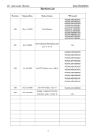
20" LCD Color Monitor Revision List Dell SP2009Wc Revision Release Date Revise history A00 May.-15-2008 Initial Release Add "Camera & Microphone test A01 Jun.-5-2008 sop" in item 6 A02 Jul.-05-2008 Add TPV Model in item 13&14 A03 Dec.-02-2008 Add TPV Model - Dell SP2009W | Service Manual - Page 3
20" LCD Color Monitor ECN History ECN No. Change Description Service Deposition Dell SP2009Wc Cut-in date MSR 3 - Dell SP2009W | Service Manual - Page 4
20" LCD Color Monitor Important Safety Notice Dell SP2009Wc Proper service and repair is important to the safe, reliable operation of all AOC Company Equipment. The service procedures recommended by AOC and described in this service manual are effective methods of performing service operations. - Dell SP2009W | Service Manual - Page 5
20" LCD Color Monitor 1. Monitor Specifications Dell SP2009Wc LCD Panel Screen type Panel Type Size Pixel pitch Viewable angle Active matrix - TFT LCD CLAA201WA04A 336 FZ CPT 20.1 inches (20.1-inch viewable image size) 0.258 mm (H) x 0.258mm(V) 160° (vertical) typ, 160° (horizontal) typ Input - Dell SP2009W | Service Manual - Page 6
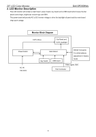
20" LCD Color Monitor 2. LCD Monitor Description Dell SP2009Wc The LCD monitor will contain a main board, power board, key board and a USB board which house the flat panel control logic, brightness control logic and DDC. The power board will provide AC to DC Inverter voltage to drive the - Dell SP2009W | Service Manual - Page 7
20" LCD Color Monitor 3. Operation instructions 3.1 Using the Front Panel Controls Use the buttons on the front of the monitor to adjust the image settings. Dell SP2009Wc Front panel Button A Preset modes B Description Use the Preset modes button to choose from a list of preset color modes. - Dell SP2009W | Service Manual - Page 8
20" LCD Color Monitor 3.2 Control Buttons Dell SP2009Wc Label Description 1 Power button 2 Capacitive touch buttons (For more information, see Operating the Monitor) 3 Webcam 4 Microphone 8 - Dell SP2009W | Service Manual - Page 9
20" LCD Color Monitor 3.3 Adjusting the Picture 1. Press the Main Menu button to open the OSD menu and display the main menu. Dell SP2009Wc 2. Press the and buttons to toggle between options in the Menu. As you move from one icon to another, the option name is highlighted. 3. To - Dell SP2009W | Service Manual - Page 10
20" LCD Color Monitor Dell SP2009Wc Back Brightness Contrast Auto Adjust Press to go back to the setup and adjust menu. The following dialog appears on a black screen as the monitor self-adjusts to the current input: Auto Adjustment allows the monitor to self-adjust to the incoming video signal. - Dell SP2009W | Service Manual - Page 11
20" LCD Color Monitor Dell SP2009Wc Input Source Use the Input Source menu to select different video signals that may be connected to your monitor. Push to go back to the main menu Select VGA input when you are using the analog (VGA) connector. Push to select the VGA input - Dell SP2009W | Service Manual - Page 12
20" LCD Color Monitor Back Press to go back to the main menu. Dell SP2009Wc Input Color Format Allows you to set the video input mode to. • RGB: Select this option if your monitor is connected to a computer The screen appears cooler with • a blue tint. • Custom (RGB): Allows you to manually - Dell SP2009W | Service Manual - Page 13
20" LCD Color Monitor • Sports: Loads color settings ideal for sports. Dell SP2009Wc • Nature: Loads color settings ideal NOTE: Saturation adjustment is available only in the Video mode. Resets your monitor's color settings to the factory defaults. DISPLAY SETTINGS Display setting mode submenu - Dell SP2009W | Service Manual - Page 14
20" LCD Color Monitor Dell SP2009Wc Horizontal position Use the and buttons to adjust image left and right Brightness control is disabled in Dynamic Contrast mode. Response time is the time required for an LCD pixel to change from fully active (black) to fully inactive (white), then back to fully - Dell SP2009W | Service Manual - Page 15
20" LCD Color Monitor • Normal • Overdrive (default). Dell SP2009Wc Display Reset Resets the monitor's display settings to the factory defaults. AUDIO SETTINGS Use the Audio Settings to adjust the audio settings. Audio Setting mode submenu Power Save Audio Allows you to turn on or off the - Dell SP2009W | Service Manual - Page 16
20" LCD Color Monitor Dell SP2009Wc Back Language Menu Transparency Menu Timer Menu Lock Press to go back to the locked except button. Button Sound DDC/CI Turns on or off the button sound. DDC/CI (Display Data Channel/Command Interface) allows a software on your computer to adjust the monitor - Dell SP2009W | Service Manual - Page 17
20" LCD Color Monitor customer experience. Dell SP2009Wc Disable: Disables the DDC/CI option and the following message appears on the screen. Select Yes to disable DDC/CI or No to return. LCD Conditioning LCD conditioning helps eliminate any image retention and may take several hours. NOTE: - Dell SP2009W | Service Manual - Page 18
20" LCD Color Monitor Dell SP2009Wc Factory Reset Personalize Resets all OSD settings to the factory preset values. Allow you to adjust shortcut key button for preset mode. Brightness & Contrast Auto Adjust and Input source. 18 - Dell SP2009W | Service Manual - Page 19
20" LCD Color Monitor OSD Warning Messages Dell SP2009Wc The following warning messages may appear on the screen to indicate that the monitor is out of synchronization. This means that the monitor cannot synchronize with the signal that it is receiving from the computer. Either the signal is too - Dell SP2009W | Service Manual - Page 20
20" LCD Color Monitor 4. Input/Output Specification 4.1 Input Signal Connector VGA Connector: Pin No. Description 1. Red Video 2. clock VGA Connector layout Dell SP2009Wc Description DVI Connector: 1 5 6 10 11 15 Note: Pin 1 is at the top right. Pin Signal Assignment 1 T.M.D.S. Data - Dell SP2009W | Service Manual - Page 21
20" LCD Color Monitor 4.2 Factory Preset Display Modes Dell SP2009Wc Display Mode VESA, 720 x 400 VESA, 640 x 480 VESA, 640 x 480 VESA, 800 x 600 VESA, 800 x 600 VESA, 1024 x 768 VESA, 1024 x 768 VESA, 1152 x - Dell SP2009W | Service Manual - Page 22
20" LCD Color Monitor 4.4 Panel Specification Dell SP2009Wc CLAA201WA04 is 20.1"(51.11cm) color TFT-LCD (Thin Film Transistor Liquid Crystal Display) module composed of LCD panel, LVDS driver ICs, control circuit and backlight(CCFL, 4 tubes). By applying 8 bit digital data (6bits+Hi-FRC), 1680× - Dell SP2009W | Service Manual - Page 23
20" LCD Color Monitor 4.5 Definition of Pixel Defects 4.5.1 Spec.of Pixel Defect Dell SP2009Wc 4.5.2 Optical Characteristics Failure Criteria 21 - Dell SP2009W | Service Manual - Page 24
20" LCD Color Monitor 4.5.3 FOS Spec. Dell SP2009Wc 24 - Dell SP2009W | Service Manual - Page 25
20" LCD Color Monitor 5. Block Diagram 5.1 Software Flow Chart 1 Y 2 3 N 4 Dell SP2009Wc 5 N Y 6 N 7 8 Y 9 10 N 11 Y N 12 N 13 Y Y N 14 15 16 Y 17 18 N 19 Y 25 - Dell SP2009W | Service Manual - Page 26
20" LCD Color Monitor 1) MCU Initializes. Dell SP2009Wc 2) Is the EEprom blank? 3) Program the signals coming from analog port? 16) Display "No connection Check Signal Cable" message. And go into standby mode after the message disappears. 17) Program the scalar to be able to show the coming - Dell SP2009W | Service Manual - Page 27
20" LCD Color Monitor 5.2 Electrical Block Diagram 5.2.1 Main Board Crystal 24MHZ (X402) Crystal 14.31818MHZ (X401) Dell SP2009Wc LCD Interface (CN402) MCU W79L659A25FL (U402) EEPROM 24LC16B/SNG (U405) EPR_SDA EPR_SCL OSD Control Interface (CN401) Scalar MST9259BH-LF-165 (Include ADC, OSD) ( - Dell SP2009W | Service Manual - Page 28
20" LCD Color Monitor 5.2.2 Inverter and Power Board AC input EMI Bridge Rectifier Transformer Dell SP2009Wc Rectifier diodes Lamp Start Circuit R932, R904, R933 PWM Control IC Over Voltage Feedback Circuit Rectify and Output DC Convert Circuit MOSFET CN902 5V 12V - Dell SP2009W | Service Manual - Page 29
20" LCD Color Monitor 6. Mechanical Instruction Dell SP2009Wc Tools: 2 Power screwdrivers(φ=5mm、L=60mm); 1 small cross screwdriver; turnbuckle driver; Setting: Power screwdriver torque A=11 kgF. Cm; torque B=6 kgF. Cm Fig Remark Remove stand: Remove the two screws and remove the stand by - Dell SP2009W | Service Manual - Page 30
20" LCD Color Monitor Dell SP2009Wc 2. Remove the two screws and remove the base by Torque A. Key board Remove the rear cover: Pry the monitor up then find out the hooks' position, use the tool (like the picture or other card) to insert into the gap of bezel and rear - Dell SP2009W | Service Manual - Page 31
20" LCD Color Monitor Dell SP2009Wc Remove shield: Remove the screws by Torque B or by manual and then remove the shield. Remove the screws remarked in red and disconnect connector remarked in green. Remove the screws and remove the main frame by manual or torque = 3kgF.Cm. LVDS cable Install: - Dell SP2009W | Service Manual - Page 32
LCD Color Monitor Power Board Main Board Dell SP2009Wc Remove the Power Board, Main Board: Remove the screws by torque B Disconnect connector remarked in green to remove the Power Board, Main Board. Install: the cable doesn't touch the capacitances and don't be laid above the capacitances. Panel - Dell SP2009W | Service Manual - Page 33
20" LCD Color Monitor Camera & Microphone test sop Preparation: open PC, Double click SP2009Cameratest Dell SP2009Wc and adsrecorder Step:1.connect monitor USB ports bring up in Fig.1 and PC USB ports with USB cable Monitor USB ports Fig 1 Step2:when appear picture in test window on screen, - Dell SP2009W | Service Manual - Page 34
20" LCD Color Monitor Dell SP2009Wc Step4: Disconnect the USB cable. Fig.3 Notices: 1.install the driver software before test PC USB ports 2. Don't touch the camera. 34 - Dell SP2009W | Service Manual - Page 35
20" LCD Color Monitor 7. Schematic Diagram 7.1 Main Board Dell SP2009Wc +3V3 FB420 +3V3_VDD +3V3 +3V3_AVDD 5,6,7 +3V3 120 Component Date 2. MCU and f unction key Thursday , April 24, 2008 OEM MODEL DELL SP2009W TPV MODEL SP2009W PCB NAME 715G3079-C Sheet 2 of 7 Size Rev 称爹 C A - Dell SP2009W | Service Manual - Page 36
20" LCD Color Monitor 219 Dell SP2009Wc + 20 21 22 23 24 25 26 27 28 29 30 CONN R427 C456 1K 1/16W 1% 0.1uF 16V C457 NC GND T P V ( Top Victory Electronics Co . , Ltd. ) G3079-D-X-X-1-080424 Key Component Date 3. Scaler Thursday , April 24, 2008 OEM MODEL DELL SP2009W TPV MODEL SP2009W - Dell SP2009W | Service Manual - Page 37
20" LCD Color Monitor Dell SP2009Wc +2V5_DMQ 3 MVREF R563 NC R564 0R05 1/16W R565 NC C499 . , Ltd. ) G3079-D-X-X-1-080424 Key Component Date 4. SDRAM Thursday , April 24, 2008 OEM MODEL DELL SP2009W TPV MODEL SP2009W PCB NAME 715G3079-B Sheet 4 of 7 37 Size Rev 称爹 Custom A - Dell SP2009W | Service Manual - Page 38
20" LCD Color Monitor Dell SP2009Wc 17 2 3 1 2 3 1 2 3 1 75R 1/16W 5% R105 75R 1/16W 5% R106 75R 1/16W 5% R107 R115 4K7 1/ Key Component Date 5. VGA&DVI input Thursday , April 24, 2008 OEM MODEL DELL SP2009W TPV MODEL SP2009W PCB NAME 715G3079-B Sheet 5 of 7 Size Rev 称爹 B A 38 - Dell SP2009W | Service Manual - Page 39
20" LCD Color Monitor +3V3 +3V3 CN701 1 BKLT_EN 2 BKLT_ADJ 3 4 5 GND 6 GND 7 +5.1V 8 +5. Ltd. ) G3079-D-X-X-1-080424 Key Component Date 6. Power Thursday , April 24, 2008 OEM MODEL DELL SP2009W TPV MODEL SP2009W PCB NAME 715G3079-C Sheet 6 of 7 Size Rev 称爹 B A Dell SP2009Wc 39 - Dell SP2009W | Service Manual - Page 40
20" LCD Color Monitor Dell SP2009Wc 2 USB_EN 2,5,6 +3V3 +5V 2,5,6 +5V +3V3 C725 0.1uF connected. GND GND T P V ( Top Victory Electronics Co . , Ltd. ) G3079-D-X-X-1-080424 Key Component Date 9. USB and CAM/MIC output Thursday , April 24, 2008 OEM MODEL DELL SP2009W TPV MODEL SP2009W - Dell SP2009W | Service Manual - Page 41
20" LCD Color Monitor 7.2 Power Board Dell SP2009Wc +1 BD901 KBP208G 2 3 4- ! 1 4 L902 L! 2 3 C902 ! 0.001uF/250V C901 0.001uF/250V FG L901 3 2 4 ! 4.0mH 1 C903 0.47uF/275V R903 R902 R901 680K 1/4W 680K 1/4W 680K 1/4W C911 0. - Dell SP2009W | Service Manual - Page 42
20" LCD Color Monitor +12V ON/OFF DIM F801 0R05 1/4W Q805 PDTC144WK C807 0. R858 33 1/4W T802 POWER X'FMR 1 8 4 3 7 9 R857 33 1/4W C840 1000pF C801 10pF/3KV C811 10pF/3KV Dell SP2009Wc 3C E2 D805 BAW56 B1 R817 10K 1/10W C819 0.0022uF R821 1K 1/10W 1% 2 3 1 R801 1K 1/10W 1% D801 - Dell SP2009W | Service Manual - Page 43
20" LCD Color Monitor 7.3 USB Board CN707 1 2 3 4 5 6 7 8 CONN 5 1 2 3 4 C732 0.1uF 6 123 4 CN705 CONNNECTOR 5 C733 0.1uF 6 123 4 1 CN706 2 CONNNECTOR 3 4 Dell SP2009Wc T P V ( Top Victory Electronics Co . , Ltd. ) G2727-D-X-X-1-080421 Key Component Date 1. USB Monday , April - Dell SP2009W | Service Manual - Page 44
20" LCD Color Monitor 7.4 Key Board VCC LED001LED002LED003LED004LED005 LED GND LED ATTN CN1 1 2 3 4 5 6 7 8 FFC CABLE Dell SP2009Wc VCC VCC SDA SCL ATTN R152 47R 1/10W 5% GND GND VDD C121 2008 OEM MODEL DELL SP2009W TPV MODEL SP2009W PCB NAME 715G3096-B Sheet 1 of 9 Size Custom Rev - Dell SP2009W | Service Manual - Page 45
20" LCD Color Monitor 8. PCB Layout 8.1 Main Board Dell SP2009Wc 45 - Dell SP2009W | Service Manual - Page 46
20" LCD Color Monitor Dell SP2009Wc 46 - Dell SP2009W | Service Manual - Page 47
20" LCD Color Monitor 8.2 Power Board Dell SP2009Wc 47 - Dell SP2009W | Service Manual - Page 48
20" LCD Color Monitor Dell SP2009Wc 8.3 USB Board 48 - Dell SP2009W | Service Manual - Page 49
20" LCD Color Monitor 9. Maintainability 9.1 Equipments and Tools Requirement 1. Voltage meter 2. Oscilloscope 3. Pattern Generator 4. LCD Color Analyzer 5. Service Manual 6. User Manual Dell SP2009Wc 49 - Dell SP2009W | Service Manual - Page 50
20" LCD Color Monitor 9.2 Trouble shooting 9.2.1 Main Board No power Dell SP2009Wc No power Press power key and look if the picture is normal OK Please reinsert and make sure the AC of 100-240 is normal - Dell SP2009W | Service Manual - Page 51
20" LCD Color Monitor No picture (LED orange) No picture Dell SP2009Wc The button if under control NG X402 oscillate NG waveform is normal Replace X402 OK Measure U701 PIN2=3V U702 PIN2=2V OK Check reset - Dell SP2009W | Service Manual - Page 52
20" LCD Color Monitor White screen White screen Dell SP2009Wc NG Measure Q708 base is high level? OK Check Q708, Q709, Q707 is broken or CN701 solder? X402 oscillate waveform is normal OK NG Check - Dell SP2009W | Service Manual - Page 53
20" LCD Color Monitor 9.2.2 Power/Inverter Board No power Check CN902 pin8,9= 5V NG Check AC line volt 110V or 220V Dell SP2009Wc OK NG Check AC input Check the voltage of C903(+) NG OK Check bridge rectified circuit and F901 circut Check start voltage for the pin3 - Dell SP2009W | Service Manual - Page 54
20" LCD Color Monitor No Backlight Check CN902 pin7, 8 = 5V OK NG Check ON/OFF signal OK NG Check IC801 PIN12=13V Dell SP2009Wc Check adapter or MB Check Interface board NG OK Change Q802, Q803 Check IC801 PIN10, 9 have the output of square wave at short time NG - Dell SP2009W | Service Manual - Page 55
20" LCD Color Monitor 9.2.3 Key Board OSD is unstable or not working Dell SP2009Wc Is Key Pad Board connecting normally? Y Is Button Switch normally? Y Is Key Pad Board normally? Y Check Main Board N Connect Key Pad Board N Replace Button Switch N Replace Key Pad Board 55 - Dell SP2009W | Service Manual - Page 56
20" LCD Color Monitor 10.White balance, Luminance adjustment Dell SP2009Wc How to setting MEM.channel you can reference to chroma 7120 user guide or simple use " SC" key and " NEXT" key to LCD-indicator on chroma 7120 will show x = 313 ±28, y = 329 ±28, Ymin=200cd/m2 4. Adjust the RED on OSD window - Dell SP2009W | Service Manual - Page 57
20" LCD Color Monitor 19. Adjust the GREEN on OSD, until chroma 7120 indicator reached G=100 Dell SP2009Wc 20. Adjust the BLUE on OSD, until chroma 7120 indicator reached B=100 21. Repeat above procedure (item 5,6,7) until chroma 7120 RGB value meet the tolerance =100±2 - Dell SP2009W | Service Manual - Page 58
20" LCD Color Monitor 11. ISP Instruction Configure and procedure It is a windows-based program, which cannot be run in MS-DOS. System and equipment requirements (1). An i486 (or above) personal computer or computer or compatible. (2). Microsoft operation system Window 95/98/2000/XP. (3). ISP Tool: - Dell SP2009W | Service Manual - Page 59
20" LCD Color Monitor Step 2: Click OK and click Read, select program Bin file, bring up Fig.3 Dell SP2009Wc Fig.3 59 - Dell SP2009W | Service Manual - Page 60
20" LCD Color Monitor Step3: Click open and OK, bring up Fig.4 and Fig.5 Dell SP2009Wc Fig.4 Fig.5 60 - Dell SP2009W | Service Manual - Page 61
20" LCD Color Monitor Step 4: Click Auto and Run, bring up Fig.6 Dell SP2009Wc Fig.6 Step 5: When appear Verify OK, writer finished as shown Fig.7 Fig.7 61 - Dell SP2009W | Service Manual - Page 62
20" LCD Color Monitor 12. Exploded View Dell SP2009Wc 62 - Dell SP2009W | Service Manual - Page 63
20" LCD Color Monitor Dell SP2009Wc item 1 2 3 4 5 6 7 8 9 10 11 Description BEZEL L20W-8DELL2 CAMERA GLASS LED LENS KEY BOARD FUNCTION LENS POWER BUTTON WEBCAM MODULE 52-04780-00A DELL-ASSIGN SCREW MIDDLE RING PANEL SCREW item 12 13 14 15 16 17 18 19 20 21 22 Description POWER BOARD SCREW MAIN - Dell SP2009W | Service Manual - Page 64
20" LCD Color Monitor 13. BOM List TA8CMUHKWMDDBZ TA8CMUNKWMDDBZ 1B0100 Dell SP2009Wc Description RUBBER WEBCAM MODULE 52-04780-00A DELL- SIGNAL CABLE DVI CABLE POWER CORD WIRE HARNESS 5P(PLUG)-5P SCREW SCREW SCREW,42-D020523 SCREW,42-D020523 SCREW,42-D020523 SCREW SCREW SCREW 42-D003574 PANEL - Dell SP2009W | Service Manual - Page 65
20" LCD Color Monitor A37G0080 1 A85G0099101 CBPC8CMUDLQ1 040G 45762412B CN709 033G3802 5B YH W CN701 3T C442 067G 305220 3T C637 067G 305220 3T C726 067G 305221 3T Dell SP2009Wc HINGE ASS'Y FOR DELL SP2008 USB STEAM SHIELD MAIN BOARD G3079-D-X-X-1-080424 CBPC LABEL WAFER WAFER FFC - Dell SP2009W | Service Manual - Page 66
20" LCD Color Monitor Dell SP2009Wc C717 067G 305470 3T 47UF +-20% 16V C730 067G 305470 3T 47UF +-20% 16V C779 067G 305470 3T 47UF +-20% 16V C783 067G 305470 3T 47UF +-20% 16V C799 067G 305470 3T 47UF +-20% 16V C713 067G 305470 3T 47UF +-20% 16V C712 067G 305470 3T 47UF +-20% - Dell SP2009W | Service Manual - Page 67
20" LCD Color Monitor Q409 057G 759 2A Q408 057G 759 2A Q407 057G 759 2A Q406 061G0402100 9F R526 061G0402100 9F R522 061G0402100 9F R520 061G0402100 9F R422 061G0402100 9F Dell SP2009Wc TANSISTOR 2N7002 SOT-23 TANSISTOR 2N7002 SOT-23 TANSISTOR 2N7002 SOT-23 TANSISTOR 2N7002 SOT - Dell SP2009W | Service Manual - Page 68
20" LCD Color Monitor R414 061G0402100 9F R587 061G0402101 R494 061G0402101 R486 061G0402101 061G0402103 R496 061G0402103 R479 061G0402103 R478 061G0402103 R475 061G0402103 R474 061G0402103 R473 061G0402103 Dell SP2009Wc RST CHIPR 0402 10 OHM +-1% 1/16W RST CHIPR 100 OHM +-5% - Dell SP2009W | Service Manual - Page 69
20" LCD Color Monitor R472 061G0402103 R471 061G0402103 R468 061G0402103 R467 061G0402103 R430 061G0402105 R766 061G0402120 2D R767 061G0402120 2D R567 061G0402150 0D R787 061G0402153 R776 061G0402153 Dell SP2009Wc RST CHIPR 10 KOHM +-5% 1/16W RST CHIPR 10 KOHM +-5% 1/16W RST - Dell SP2009W | Service Manual - Page 70
20" LCD Color Monitor R775 061G0402153 R774 061G0402153 R773 061G0402153 R129 061G0402220 R568 061G0402472 R125 061G0402472 R506 061G0402472 R115 061G0402472 R116 061G0402472 R117 061G0402472 R124 061G0402472 Dell SP2009Wc RST CHIP 15K 1/16W 5% RST CHIP 15K 1/16W 5% RST CHIP - Dell SP2009W | Service Manual - Page 71
20" LCD Color Monitor R599 061G0402472 R598 061G0402472 R785 061G0402472 R722 061G0402472 32 C498 065G0402104 12 C499 065G0402104 12 C503 065G0402104 12 C504 065G0402104 12 C505 065G0402104 12 Dell SP2009Wc RST CHIPR 4.7 KOHM +-5% 1/16W RST CHIPR 4.7 KOHM +-5% 1/16W RST CHIPR 4.7 - Dell SP2009W | Service Manual - Page 72
20" LCD Color Monitor C506 065G0402104 12 C507 065G0402104 12 C508 065G0402104 12 C509 065G0402104 12 C705 065G0402104 12 C704 065G0402104 12 C510 065G0402104 12 C512 0.1UF 16V X7R CAP CHIP 0402 0.1UF 16V X7R CAP CHIP 0402 0.1UF 16V X7R CAP CHIP 0402 0.1UF 16V X7R Dell SP2009Wc 72 - Dell SP2009W | Service Manual - Page 73
20" LCD Color Monitor C759 065G0402104 12 C760 065G0402104 12 C763 065G0402104 12 C765 065G0402104 12 C767 065G0402104 12 C782 065G0402104 12 C446 065G0402104 12 C781 0.1UF 16V X7R CAP CHIP 0402 0.1UF 16V X7R CAP CHIP 0402 0.1UF 16V X7R CAP CHIP 0402 0.1UF 16V X7R Dell SP2009Wc 73 - Dell SP2009W | Service Manual - Page 74
20" LCD Color Monitor C426 065G0402104 12 C423 065G0402104 12 C421 065G0402104 12 C420 065G0402104 12 C417 065G0402104 12 C415 065G0402104 12 C413 065G0402104 12 C411 0402 0.1UF 16V X7R CAP CHIP 0402 0.1UF 16V X7R CHIP 22PF 50V NPO CHIP 22PF 50V NPO CHIP 22PF 50V NPO Dell SP2009Wc 74 - Dell SP2009W | Service Manual - Page 75
20" LCD Color Monitor C752 065G0402220 31 C761 065G0402220 31 C762 065G0402220 31 C424 071G 56K121 FB702 071G 56K121 FB701 071G 56K121 FB421 071G 56K121 FB420 071G 56K121 FB401 071G 56V301 B Dell SP2009Wc CHIP 22PF 50V NPO CHIP 22PF 50V NPO CHIP 22PF 50V NPO CHIP 22PF 50V NPO CHIP - Dell SP2009W | Service Manual - Page 76
20" LCD Color Monitor FB402 071G 56V301 B FB403 071G 56V301 B FB404 071G 56V301 B FB405 071G 56V301 B 6433P D506 093G 6433P D507 093G 6433P D504 093G 6433P D505 093G 6433P Dell SP2009Wc CHIP BEAD FCM2012VF-301T07 BULLWILL CHIP BEAD FCM2012VF-301T07 BULLWILL CHIP BEAD FCM2012VF- - Dell SP2009W | Service Manual - Page 77
20" LCD Color Monitor D508 093G 6433P D509 093G 6433P ZD103 093G 39S 24 T ZD102 093G 39S 24 T ZD101 14 31 EL LED003 081G 14 31 EL LED005 081G 14 31 EL LED004 081G 14 31 EL 715G3096 D HF Dell SP2009Wc BAV99 BAV99 RLZ 5.6B LLDS RLZ 5.6B LLDS RLZ 5.6B LLDS RLZ 5.6B LLDS RLZ 5.6B LLDS RLZ - Dell SP2009W | Service Manual - Page 78
20" LCD Color Monitor R155 061G0603101 C131 065G0603209 21 C132 065G0603209 21 PWPC8A42CQA1 040G 45762412B 088G 304 8K C Dell SP2009Wc RST CHIPR 100 OHM +-5% 1/10W CHIP 2PF 25V NPO CHIP 2PF 25V NPO POWER G2778-I-X-X-3-080425 CBPC LABEL NYLON-SPACER SUPPORT PORON INVERTER INVERT CONNECTOR - Dell SP2009W | Service Manual - Page 79
20" LCD Color Monitor CN902 095G 82012D507 705GQ793064 Q900 057G 667 21 HS1 090G6281 1 BD901 061G0603100 1F R821 061G0603100 1F R818 061G0603100 1F R812 061G0603100 1F R809 061G0603100 1F Dell SP2009Wc WIRE HARNESS 12P(SAN)-12P(PLUG) BD901/Q900 ASS'Y STP10NK70ZFP HEAT SINK BRIDGE - Dell SP2009W | Service Manual - Page 80
20" LCD Color Monitor R803 061G0603105 R835 061G0603105 R862 061G0603105 R831 061G0603240 1F 1F R814 061G0805150 1F R815 061G0805150 1F R816 061G0805150 1F R929 061G0805240 1F R810 061G0805300 2F Dell SP2009Wc RST CHIPR 1M OHM +-5% 1/10W RST CHIPR 1M OHM +-5% 1/10W RST CHIPR 1M - Dell SP2009W | Service Manual - Page 81
20" LCD Color Monitor R926 061G0805330 2F R825 061G0805390 R829 061G0805390 R924 061G0805390 1F 22 C821 065G0603104 22 C825 065G0603104 22 C834 065G0603104 22 C815 065G0603222 22 C816 065G0603222 22 Dell SP2009Wc RST CHIPR 33K OHM +-1% 1/8W RST CHIPR 39 OHM +-5% 1/8W RST CHIPR 39 - Dell SP2009W | Service Manual - Page 82
20" LCD Color Monitor C819 065G0603222 22 C823 065G0603222 22 C928 093G 64S511SEM D809 093G 64S511SEM D814 093G 64S511SEM D817 093G 64S511SEM D922 093G 64S511SEM D923 093G 64S511SEM Dell SP2009Wc CHIP 2200PF 25V X7R CHIP 2200PF 25V X7R CHIP 1000P 50VX7R 0805 CAP CHIP 0805 0.1UF K - Dell SP2009W | Service Manual - Page 83
20" LCD Color Monitor Q44GA053700 1A Q44GSLIP10076A Q45G 88609154 Q45G 88609155 Dell SP2009Wc EYELET KIA431A-AT/P TO-92 1K OHM DELL LOGO CAMERA GLASS RATING LABEL PALLET LABEL DELL CARTON LABEL SP2009W QSG FOR WEST PIG FOR DAO PAPER BOARD PAPER CAP CORNER PAPER PULP MOLD PULP MOLD 20 LCD DELL - Dell SP2009W | Service Manual - Page 84
SP2009Wc BIG TAPE FOR DELL CARTON 3M DOUBLE FACE TAPE EPE PROTECT FILM SP2009W CD MANUAL FFC CABLE 1.0*30*2.5-165-3-0.65*0.05 F1010HA-30P-BK 1.0S-19-30A USB BPARD PCB G2727-D-X-X-1-080421 WAFER USB CONNECTOR A TYPE REVERSE USB CONNECTOR A TYPE REVERSE 0.1UF +-20% 50V Y5V 0.1UF +-20% 50V Y5V USB PCB - Dell SP2009W | Service Manual - Page 85
20" LCD Color Monitor 14. Different Parts List Dell SP2009Wc Diversity of TA8GMUHKWMDDBZ compared with TA8CMUHKWMDDBZ Location Part No. Description E08911 089G179E30NA11 FFC CABLE E750L 750GLGA1W3J21Z000D PANEL LM201WE3-TLJ1 KR LPL E750L 750GLGA1W3J32Z000D PANEL SP2009W QSG FOR EAST 85 - Dell SP2009W | Service Manual - Page 86
20" LCD Color Monitor Q41G7800700A28 Q44GA053700 2B E08911 S89G179T30NA11 071FW100001012 044F3231 167C4 PIG FOR APCC 20 LCD DELL CTN LVDS ASSY 40*12*6.5-1.5+h/s 5760 30*10*0.8 Dell SP2009Wc 750GLCA1WAA33D000D PANEL CLAA201WA04A 336 FZ CPT Q41G780070071A DVI sheet Q41G7800700A26 SP2009W QSG FOR - Dell SP2009W | Service Manual - Page 87
20" LCD Color Monitor Dell SP2009Wc Diversity of TA8CMUNJWMDDBC compared with TA8CMUHKWMDDBZ Location Part No. Description 044G9003194 CORNER PAPER 089G401A18NHRA POWER CORD E750 750GLCA1WAA33D000D Q07G 1 5D36 X Q41G7800700A26 PANEL CLAA201WA04A 336 FZ CPT WOODEN PALLET SP2009W - Dell SP2009W | Service Manual - Page 88
20" LCD Color Monitor Dell SP2009Wc Diversity of TA8CMUNMWMDLBC compared with TA8CMUHKWMDDBZ Location Part No. Description E750 750GLCA1WAA33D000D PANEL CLAA201WA04A 336 FZ CPT Q41G7800700A26 SP2009W QSG FOR EAST Q41G7800700A28 PIG FOR APCC Diversity of TA8GMUNFWMDLBC compared with - Dell SP2009W | Service Manual - Page 89
20" LCD Color Monitor Dell SP2009Wc Diversity TA8GMUHKWMDDBC of compared with TA8CMUHKWMDDBZ Location Part No. Description E08911 089G179E30NA11 FFC CABLE 0M1G3130 5125 SCREW E750L 750GLGA1W3J21D000D PANEL LM201WE3-TLJ1 KR LGD E750L 750GLGA1W3J32D000D PANEL LM201WE3-TLJ3 NJ LGD - Dell SP2009W | Service Manual - Page 90
20" LCD Color Monitor Dell SP2009Wc Diversity of TA8CMUNKWMDDBC compared with TA8CMUHKWMDDBZ Location Part No. Description E750 750GLCA1WAA32D000D PANEL CLAA201WA04A 336 WJ CPT E750 750GLCA1WAA33D000D PANEL CLAA201WA04A 336 FZ CPT E750 750GLCA1WAA42D000D PANEL CLAA201WA04A 347 WJ CPT E750 - Dell SP2009W | Service Manual - Page 91
20" LCD Color Monitor C811 065G 6J5096ET C801 065G 6J5096ET L921 073G 253 91 H L922 073G 253 91 H Q41G7800700A29 E08911 S89G179T30NA11 071FW100001012 044F3231 167C4 CAP CER 5PF J 6KV CAP CER 5PF J 6KV CHOKE COIL CHOKE COIL PIG FOR EMEA LVDS ASSY 40*12*6.5-1.5+h/s 5760 30*10*0.8 Dell - Dell SP2009W | Service Manual - Page 92
20" LCD Color Monitor Diversity of TA8CMUNBWMDDBZ compared with TA8CMUHKWMDDBZ Location Part No. Description Q41G7800700A29 PIG FOR EMEA Dell SP2009Wc ASS'Y 705GQ8SK040 20" DELL SKD BEZEL ASS'Y E750L 750GLGA1W3J21D000D PANEL LM201WE3-TLJ1 KR LGD E750L 750GLGA1W3J32D000D PANEL LM201WE3-TLJ3 - Dell SP2009W | Service Manual - Page 93
20" LCD Color Monitor Dell SP2009Wc Diversity of TA8CMUNBWMDD4C compared with TA8CMUHKWMDDBZ Location Part No. Description 044G9003194 CORNER PAPER 052G 1185 1 BIG TAPE E750 750GLCA1WAA32D000D PANEL CLAA201WA04A 336 WJ CPT E750 750GLCA1WAA33D000D PANEL CLAA201WA04A 336 FZ CPT E750 - Dell SP2009W | Service Manual - Page 94
20" LCD Color Monitor R861 061G0603150 3F Q41G7800700A62 Q41G7800700A73 Q70G2002700 4C S89G179T30NA11 RST CHIPR 150 KOHM +-1% 1/10W PIG FOR DAO TECH SHEET FOR SP2009WC SP2009W CD MANUAL LVDS ASSY Dell SP2009Wc 94
-
 1
1 -
 2
2 -
 3
3 -
 4
4 -
 5
5 -
 6
6 -
 7
7 -
8
-
9
-
10
-
11
-
12
-
13
-
14
-
15
-
16
-
17
-
18
-
19
-
20
-
21
-
22
-
23
-
24
-
25
-
26
-
27
-
28
-
29
-
30
-
31
-
32
-
33
-
34
-
35
-
36
-
37
-
38
-
39
-
40
-
41
-
42
-
43
-
44
-
45
-
46
-
47
-
48
-
49
-
50
-
51
-
52
-
53
-
54
-
55
-
56
-
57
-
58
-
59
-
60
-
61
-
62
-
63
-
64
-
65
-
66
-
67
-
68
-
69
-
70
-
71
-
72
-
73
-
74
-
75
-
76
-
77
-
78
-
79
-
80
-
81
-
82
-
83
-
84
-
85
-
86
-
87
-
88
-
89
-
90
-
91
-
92
-
93
-
94
 |
 |
20" LCD Color Monitor
Dell SP2009Wc
1
Service
Service
Service
Horizontal Frequency
30 kHz to 83 kHz
Table Of Contents
Description
Page
Description
Page
SAFETY NOTICE
ANY PERSON ATTEMPTING TO SERVICE THIS CHASSIS MUST FAMILIARIZE HIMSELF WITH THE
CHASSIS AND BE AWARE OF THE NECESSARY SAFETY PRECAUTIONS TO BE USED WHEN SERVICING
ELECTRONIC EQUIPMENT CONTAINING HIGH VOLTAGES.
6.Mechanical Instruction………………..…..…
.......
29
7.Schematic Diagram………
..................................
…
.....
35
7.1Main Board
......
………
......................................
35
7.2 Power Board……..…….……
....................................
41
7.3 USB Board……………………………………………..43
7.4 Key Board………………………...…………………….44
8.PCB Layout..……...…………
.......................................
45
8.1.Main Board……………..…
........................................
45
8.2.Power Board……………
........................................
47
8.3.USB Board…………………
.....................................
48
9.Maintainability…………
.......................................
49
9.1.Equipments and Tools Requirement..…….…
...........
49
9.2.Trouble Shooting…………………
.............................
50
10.White-Balance, Luminance adjustment...………
......
56
11.ISP Instruction…………….……
.................................
58
12.Monitor Exploded View…………….…………
............
62
13.BOM List…………
.....................................................
64
14.Different Parts List…………………….……………...85
CAUTION: USE A SEPARATE ISOLATION TRANSFOMER FOR THIS UNIT WHEN SERVICING
Table Of Contents
.......
……
.................
……
...........
…
........
1
Revision List.…
.........................
………
................
……
......
2
ECN History.…
.......................
………
..................
……
......
3
Important Safety Notice.….……….…
..................
……
......
4
1.Monitor Specifications
.....
…
........................
………
........
5
2.LCD Monitor Description……………………………
.......
6
3.Operation Instructions……………
...............
……
...........
7
3.1.General Instructions…………………………………….7
3.2.Control Buttons……………
...............
……
...............
8
3.3 Adjusting the Picture
...........
……………
.........
………..9
4.Input/Output Specification
.............
……………
........
…20
4.1.Input Signal Connector
............
…………
.................
20
4.2.Factory Preset Display Modes...…..…
......................
21
4.3.Power Supply Requirements
..........
……
...................
21
4.4.Panel Specification……
.....
……………
..................
22
4.5.Definition of Pixel Defects…………
...............
……….23
5.Block Diagram…….…
...................
…………
................
25
5.1.Software Flow Chart………..………………
....
…
.......
25
5.2.Electrical Block Diagram………………..…..…
.......
27