Dell STUDIO XPS 16 Service Manual
Dell STUDIO XPS 16 - OBSIDIAN - NOTEBOOK Manual
 |
UPC - 067540444442
View all Dell STUDIO XPS 16 manuals
Add to My Manuals
Save this manual to your list of manuals |
Dell STUDIO XPS 16 manual content summary:
- Dell STUDIO XPS 16 | Service Manual - Page 1
Dell™ Studio XPS™ 1640 Service Manual Before You Begin Base Cover Hard Drive Rear Caps Processor Heat Sink Processor Thermal Fan Memory Coin-Cell Battery Wireless Mini-Card Palm Rest Keyboard Speakers Optical Drive Display Assembly IEEE 1394 Module Subwoofer Audio Board System Board TV Tuner Card - Dell STUDIO XPS 16 | Service Manual - Page 2
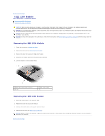
Back to Contents Page IEEE 1394 Module Dell™ Studio XPS™ 1640 Service Manual Removing the IEEE 1394 Module Replacing the IEEE 1394 Module CAUTION: Before working inside your computer, read the safety information that shipped with your computer. - Dell STUDIO XPS 16 | Service Manual - Page 3
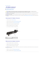
Back to Contents Page AC Adapter Connector Dell™ Studio XPS™ 1640 Service Manual Removing the AC Adapter Connector Replacing the AC Adapter Connector CAUTION: Before working inside your computer, read the safety information that shipped with your computer. - Dell STUDIO XPS 16 | Service Manual - Page 4
Back to Contents Page - Dell STUDIO XPS 16 | Service Manual - Page 5
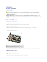
Back to Contents Page Audio Board Dell™ Studio XPS™ 1640 Service Manual Removing the Audio Board Replacing the Audio Board CAUTION: Before working inside your computer, read the safety information that shipped with your computer. For additional - Dell STUDIO XPS 16 | Service Manual - Page 6
4. Replace the device status lights board mylar. 5. Replace the audio grounding cable and connect it to the system board and audio board connectors. NOTICE: Before turning on the computer, replace all screws and ensure that no stray screws remain inside the computer. Failure to do so may result in - Dell STUDIO XPS 16 | Service Manual - Page 7
Back to Contents Page Base Cover Dell™ Studio XPS™ 1640 Service Manual Removing the Base Cover Replacing the Base Cover CAUTION: Before working inside your computer, read the safety information that shipped with your computer. For additional - Dell STUDIO XPS 16 | Service Manual - Page 8
Page Battery Latch Assembly Dell™ Studio XPS™ 1640 Service Manual Removing the Battery Latch Assembly Replacing the Battery Latch Assembly NOTICE: Only a certified service technician should perform repairs on your computer. Damage due to servicing that is not authorized by Dell™ is not covered by - Dell STUDIO XPS 16 | Service Manual - Page 9
- Dell STUDIO XPS 16 | Service Manual - Page 10
Back to Contents Page Before You Begin Dell™ Studio XPS™ 1640 Service Manual Recommended Tools Turning Off Your Computer Before Working Inside Your Computer This section provides procedures for removing and installing the components in your computer. Unless - Dell STUDIO XPS 16 | Service Manual - Page 11
to the system board, you must remove the battery from the battery bay before you service the computer. NOTICE: To avoid damage to the computer, use only the battery designed for this particular Dell computer. Do not use batteries designed for other Dell computers. 7. Turn the computer over. 8. Slide - Dell STUDIO XPS 16 | Service Manual - Page 12
Dell™ Studio XPS™ 1640 Service Manual CD, and restart the computer. Follow the instructions that appear on the screen. The computer continues battery is properly installed, and a network cable is attached. 2. Turn on the computer. 3. Locate the latest BIOS update file for your computer at support.dell - Dell STUDIO XPS 16 | Service Manual - Page 13
- Dell STUDIO XPS 16 | Service Manual - Page 14
Coin-Cell Battery Dell™ Studio XPS™ 1640 Service Manual Removing the Coin-Cell Battery Replacing the Coin-Cell Battery CAUTION: Before NOTICE: Only a certified service technician should perform repairs on your computer. Damage due to servicing that is not authorized by Dell™ is not covered by your - Dell STUDIO XPS 16 | Service Manual - Page 15
Back to Contents Page Processor Dell™ Studio XPS™ 1640 Service Manual Removing the Processor Installing the Processor CAUTION: Before working inside your computer, read the safety information that shipped with your computer. For additional safety best practices information, see the Regulatory - Dell STUDIO XPS 16 | Service Manual - Page 16
heat sink (see Replacing the Processor Heat Sink). 5. Replace the rear caps (see Replacing the Rear Caps). 6. Replace the base cover (see Replacing the Base Cover). 7. Slide the battery into the battery bay until it clicks into place. 8. Update the BIOS using a BIOS upgrade CD (see Flashing - Dell STUDIO XPS 16 | Service Manual - Page 17
Back to Contents Page Processor Heat Sink Dell™ Studio XPS™ 1640 Service Manual Removing the Processor Heat Sink Replacing the Processor Heat Sink CAUTION: Before working inside your computer, read the safety information that shipped with your computer. For additional safety best practices - Dell STUDIO XPS 16 | Service Manual - Page 18
Back to Contents Page - Dell STUDIO XPS 16 | Service Manual - Page 19
Dell™ Studio XPS™ 1640 Service Manual battery (see Before Working Inside Your Computer) before working inside the computer. NOTICE: To avoid damage to the display, you must not disassemble your Edge-to-Edge display assembly in the field. Removing the Display Assembly 1. Follow the instructions - Dell STUDIO XPS 16 | Service Manual - Page 20
assembly in position and replace the four screws (two on either side) that secure the display assembly. 2. Place the right power/battery light cable, left power/battery light cable, display cable, and camera cable in the routing guides and connect them to the respective system board connectors. - Dell STUDIO XPS 16 | Service Manual - Page 21
rest and through the system board. 4. Replace the two screws on the computer base. 5. Route the Mini-Card antenna cables through their routing guides in the computer base. 6. Replace the optical drive (see Replacing the Optical Drive). 7. Replace the palm rest (see Replacing the Palm Rest). NOTICE - Dell STUDIO XPS 16 | Service Manual - Page 22
Contents Page eSATA Connector Dell™ Studio XPS™ 1640 Service Manual Removing the eSATA Connector instructions in Before You Begin. 2. Remove the system board (see Removing the System Board). 3. Remove the screw that secures the eSATA connector. 4. Remove the eSATA cable from the routing guide - Dell STUDIO XPS 16 | Service Manual - Page 23
Back to Contents Page Thermal Fan Dell™ Studio XPS™ 1640 Service Manual Removing the Thermal Fan Replacing the Thermal Fan CAUTION: Before working inside your computer, read the safety information that shipped with your computer. For additional - Dell STUDIO XPS 16 | Service Manual - Page 24
processor, thermal fan, or system board is replaced, use the thermal cooling pads provided in the kit on the processor heat sink to ensure that thermal conductivity is achieved. Do not reuse the old thermal cooling pads. 5. Replace the processor heat sink (see Replacing the Processor - Dell STUDIO XPS 16 | Service Manual - Page 25
Back to Contents Page Hard Drive Dell™ Studio XPS™ 1640 Service Manual Removing the Hard Drive Replacing the Hard Drive CAUTION: If you remove the hard drive from the computer when the drive is hot, do not - Dell STUDIO XPS 16 | Service Manual - Page 26
the computer. Failure to do so may result in damage to the computer. 7. Slide the battery into the battery bay until it clicks into place. 8. Install the operating system for your computer, as needed (see Dell Technology Guide). 9. Install the drivers and utilities for your computer, as needed (see - Dell STUDIO XPS 16 | Service Manual - Page 27
- Dell STUDIO XPS 16 | Service Manual - Page 28
Back to Contents Page Keyboard Dell™ Studio XPS™ 1640 Service Manual Removing the Keyboard Replacing the Keyboard CAUTION: Before working inside your computer, read the safety information that shipped with your computer. For additional safety best - Dell STUDIO XPS 16 | Service Manual - Page 29
3. Replace the thirteen screws that secure the keyboard to the palm rest. NOTICE: The keycaps on the keyboard are fragile, easily dislodged, and time-consuming to replace. Be careful when removing and handling the keyboard. 4. Replace the palm rest (Replacing the Palm Rest). Back to Contents Page - Dell STUDIO XPS 16 | Service Manual - Page 30
Back to Contents Page Memory Dell™ Studio XPS™ 1640 Service Manual Removing the Memory Module(s) Replacing the Memory Module(s) CAUTION: Before working inside your computer, read the safety information that shipped with your computer. For additional safety best practices information, see the - Dell STUDIO XPS 16 | Service Manual - Page 31
base cover (see Replacing the Base Cover). 4. Slide the battery into the battery bay, or connect the AC adapter to your computer and memory and automatically updates the system configuration information. To confirm the amount of memory installed in the computer, click Start ® Help and Support® Dell - Dell STUDIO XPS 16 | Service Manual - Page 32
Contents Page Wireless Mini-Card Dell™ Studio XPS™ 1640 Service Manual Removing the Mini-Card Replacing the battery (see Before Working Inside Your Computer) before working inside the computer. NOTE: Dell does not guarantee compatibility or provide support for Mini-Cards from sources other than Dell - Dell STUDIO XPS 16 | Service Manual - Page 33
provides the antenna cable color scheme for the MiniCard supported by your computer. Connectors on the Mini-Card WWAN battery into the battery bay until it clicks into place. 9. Install the drivers and utilities for your computer, as required. For more information, see the Dell Technology Guide - Dell STUDIO XPS 16 | Service Manual - Page 34
- Dell STUDIO XPS 16 | Service Manual - Page 35
Back to Contents Page Optical Drive Dell™ Studio XPS™ 1640 Service Manual Removing the Optical Drive Replacing the Optical Drive CAUTION: Before working inside your computer, read the safety information that shipped with your computer. For additional - Dell STUDIO XPS 16 | Service Manual - Page 36
1 interposer Replacing the Optical Drive 1. Attach the interposer to the optical drive. 2. Place the optical drive in the computer base. 3. Replace the three screws that secure the optical drive to the system board. 4. Turn the computer over and replace the screw that secures the optical drive to - Dell STUDIO XPS 16 | Service Manual - Page 37
Back to Contents Page Palm Rest Dell™ Studio XPS™ 1640 Service Manual Removing the Palm Rest Replacing the Palm Rest CAUTION: Before working inside your computer, read the safety information that shipped with your computer. For additional - Dell STUDIO XPS 16 | Service Manual - Page 38
(see Replacing the Rear Caps). 6. Replace the base cover (see Replacing the Base Cover). 7. Reinstall the ExpressCards in the ExpressCard slot, if any. 8. Slide the battery into the battery bay until it clicks into place. Back to Contents Page - Dell STUDIO XPS 16 | Service Manual - Page 39
Back to Contents Page Rear Caps Dell™ Studio XPS™ 1640 Service Manual Removing the Rear Caps Replacing the Rear Caps CAUTION: Before working inside your computer, read the safety information that shipped with your computer. For additional - Dell STUDIO XPS 16 | Service Manual - Page 40
Back to Contents Page Speakers Dell™ Studio XPS™ 1640 Service Manual Removing the Speakers Replacing the Speakers CAUTION: Before working inside your computer, read the safety information that shipped with your computer. For additional safety best - Dell STUDIO XPS 16 | Service Manual - Page 41
Back to Contents Page - Dell STUDIO XPS 16 | Service Manual - Page 42
Back to Contents Page Subwoofer Dell™ Studio XPS™ 1640 Service Manual Removing the Subwoofer Replacing the Subwoofer CAUTION: Before working inside your computer, read the safety information that shipped with your computer. For additional safety best - Dell STUDIO XPS 16 | Service Manual - Page 43
Dell™ Studio XPS™ 1640 Service Manual Removing memory module(s) (see Removing the Memory Module(s)). 6. Remove the processor heat sink (see Removing the Processor Heat Sink). 7. Remove the thermal fan (see Removing the Thermal Fan). 8. Remove the coin-cell battery (see Removing the Coin-Cell Battery - Dell STUDIO XPS 16 | Service Manual - Page 44
the right power/battery light cable, left power/battery light cable, display cable, and camera cable in the routing guides and connect them Replace the processor heat sink (see Replacing the Processor Heat Sink). 15. Replace the memory module(s) (see Replacing the Memory Module(s)). 16. Replace the - Dell STUDIO XPS 16 | Service Manual - Page 45
: After you have replaced the system board, enter the computer Service Tag into the BIOS of the replacement system board. 20. Insert the BIOS upgrade CD that accompanied the replacement system board into the appropriate drive. Follow the instructions that appear on the screen. Back to Contents Page - Dell STUDIO XPS 16 | Service Manual - Page 46
to Contents Page Dell™ Studio XPS™ 1640 Service Manual NOTE: A NOTE indicates important information that helps you make better use of your computer. NOTICE: A NOTICE indicates either potential damage to hardware or loss of data and tells you how to avoid the problem. CAUTION: A CAUTION indicates - Dell STUDIO XPS 16 | Service Manual - Page 47
Dell™ Studio XPS™ 1640 Service Manual battery (see Before Working Inside Your Computer) before working inside the computer. NOTE: The availability of the TV Tuner card varies according to region. Removing the TV Tuner Card 1. Follow the instructions card cable in the routing guide and connect it to
-
 1
1 -
 2
2 -
 3
3 -
 4
4 -
 5
5 -
 6
6 -
 7
7 -
8
-
9
-
10
-
11
-
12
-
13
-
14
-
15
-
16
-
17
-
18
-
19
-
20
-
21
-
22
-
23
-
24
-
25
-
26
-
27
-
28
-
29
-
30
-
31
-
32
-
33
-
34
-
35
-
36
-
37
-
38
-
39
-
40
-
41
-
42
-
43
-
44
-
45
-
46
-
47
 |
 |
Dell™ Studio XPS™ 1640 Service Manual
Notes, Notices, and Cautions
Information in this document is subject to change without notice.
© 2008 Dell Inc. All rights reserved.
Reproduction of these materials in any manner whatsoever without the written permission of Dell Inc. is strictly forbidden.
Trademarks used in this text:
Dell
,
XPS
, and the
DELL
logo are trademarks of Dell Inc.;
Bluetooth
is a registered trademark owned by Bluetooth SIG, Inc. and is used by Dell under
license.
Microsoft
,
Windows
,
Windows Vista
,
and
Windows Vista start button logo
are either trademarks or registered trademarks of Microsoft Corporation in the United States and/or
other countries.
Other trademarks and trade names may be used in this document to refer to either the entities claiming the marks and names or their products. Dell Inc. disclaims any
proprietary interest in trademarks and trade names other than its own.
Model PP35L
December 2008 Rev. A00
Before You Begin
Base Cover
Hard Drive
Rear Caps
Processor Heat Sink
Processor
Thermal Fan
Memory
Coin
-
Cell Battery
Wireless Mini
-
Card
Palm Rest
Keyboard
Speakers
Optical Drive
Display Assembly
IEEE 1394 Module
Subwoofer
Audio Board
System Board
TV Tuner Card (Optional)
eSATA Connector
AC Adapter Connector
Battery Latch Assembly
Flashing the BIOS
NOTE:
A NOTE indicates important information that helps you make better use of your computer.
NOTICE:
A NOTICE indicates either potential damage to hardware or loss of data and tells you how to avoid the problem.
CAUTION:
A CAUTION indicates a potential for property damage, personal injury, or death.