Dell W2306C Service Manual
Dell W2306C Manual
 |
View all Dell W2306C manuals
Add to My Manuals
Save this manual to your list of manuals |
Dell W2306C manual content summary:
- Dell W2306C | Service Manual - Page 1
Dell W2306C SERVICE MANUAL LCD TV MONITOR W2306C THESE DOCUMENTS ARE FOR REPAIR SERVICE INFORMATION ONLY. EVERY REASONABLE EFFORT HAS BEEN MADE TO ENSURE THE ACCURACY OF THIS MANUAL; WE CANNOT GUARANTEE THE ACCURACY OF THIS INFORMATION AFTER THE DATE OF PUBLICATION AND DISCLAIMS RELIABILITY FOR - Dell W2306C | Service Manual - Page 2
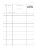
Revision List Dell W2306C Version A00 A01 A02 Release Date Sep-15-2005 Oct-24-2005 Revision Instructions TPV Model Initial Release EDF5GGNKDEDMJMP EDF5SGNKDEDBJMP Second Version (Remark: Add the Operation Instructions and Repair Flow Chart) April-25-2006 Add "Max - Dell W2306C | Service Manual - Page 3
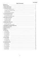
Revision List Dell W2306C Table Of Contents ...1 Table Of Contents ...2 1. General Specifications ...3 2. Operating Instructions ...4 2.1 The Use Of Remote Control ...4 2.2 Panel Control Knobs and Ports 7 2.3 OSD Operating ...11 2.4 Connecting LCD TV Display ...17 3. Input /Output - Dell W2306C | Service Manual - Page 4
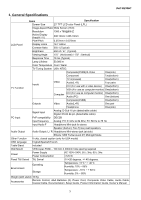
XT; Midnight Mode Other Function V-chip, closed caption (only for USA model) OSD language English/Spanish/French Table Stand Included Wall Mount VESA spec FDMI - 100 mm X 200mm hole spacing required Power Power Supply Power Consumption AC 100V~240V, 50 ± 3Hz, 60 ± 3Hz - Dell W2306C | Service Manual - Page 5
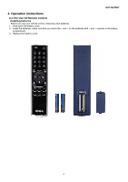
Dell W2306C 2. Operation Instructions 2.1 The Use Of Remote Control Installing batteries Before you use your remote control, install two-AAA batteries. 1. Slide open the battery cover. 2. Install the batteries, make sure that you match the + and - on the batteries with + and - symbols - Dell W2306C | Service Manual - Page 6
Dell W2306C 5 - Dell W2306C | Service Manual - Page 7
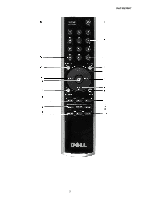
Dell W2306C 1 Power Button Turns the LCD TV display on and off 2 Number Button Press to select a channel 3 Enter Select a TV menu option, confirm a channel selection 4 Mute Press to turn the sound on and off 5 CH (up icon) Push to view the next channel In the TV menu, use the channel button - Dell W2306C | Service Manual - Page 8
2.2 Front Panel Control Knobs Front View Dell W2306C 1. IR receiver Senses the signal 2. Power indicator (LED) The light is blue when the LCD TV is on and amber when the LCD TV display is in power save mode. 7 - Dell W2306C | Service Manual - Page 9
Right Side View Dell W2306C 1. Power button Push to turn the LCD TV display on and off, the power button is blue when it is on and amber when it is in power saving mode 2. TV menu button Push to enable the TV menu 3. Volume button Push to decrease the volume 4. Volume button Push to - Dell W2306C | Service Manual - Page 10
Left Side View Dell W2306C 1. AV Side (S-Video 1) Connect devices such as a video game system or a VCR. 2. AV Side (Composite 1) Connect devices such as a VCR or DVD player 3. Composite audio - Dell W2306C | Service Manual - Page 11
Dell W2306C 1. Power TV box. Use the DVI audio connector if you have connected a device such as a DVD player to the DVI connector. Connect your computer Connect your computer or video devices such as a DVD player Connect the audio cable from your computer to the LCD TV display. Connect cable TV - Dell W2306C | Service Manual - Page 12
Using Remote Control With the TV Menu Dell W2306C 1. To enter the TV menu, press the menu button. Seven icons appear along the bottom of the screen. 2. Move the left and right buttons (volume buttons) to move between the icons. The icon appears highlighted as you move through the menu. 3. To - Dell W2306C | Service Manual - Page 13
Select TV Menu Dell W2306C The Input Select menu allows you toe select the proper source based on how you have you LCD TV display and video equipment connected. Press Input on the remote to go directly to the Input Select menu.You can also press menu and select Input select from the main menu. VGA - Dell W2306C | Service Manual - Page 14
Picture TV Menu Dell W2306C The picture menu allows you to adjust the appearance of the image and color. The color temperature presets are: Natural: 6500K Normal: The native panel temperature: Blue: 9300K Red: 5700K Audio The audio menu allows you to set the audio to best fit the type of show - Dell W2306C | Service Manual - Page 15
for viewing TV VCR or 4:3 DVD movie. 4:3 - Best selection for viewing digital HDTV, VCR or 4:3 DVD movies. WIDE - Best selection for viewing digital HDTV, 16:9 or 22:9 DVD movies. FULL SCREEN -Best selection for viewing digital HDTV, or 16:9 DVD movies. Parental Control Parental Control allows you - Dell W2306C | Service Manual - Page 16
on the remote control, enter a new access code. 3.Select Exit. TV Menu Setup TV Menu Setup allows you to adjust the appearance of the TV menu, to change the language of the TV menu and to restore factory setting. Use the TV menu setting menu you can select TV Button lock to lock the TV menu and the - Dell W2306C | Service Manual - Page 17
of time after which the LCD TV display turns off automatically. You can select from 10 minutes to 3 hours Closed Caption In the Closed Caption menu, you can select on, off, or Mute. If you select Music automatically displays when you use the mute button on the remote control. You can choose from - Dell W2306C | Service Manual - Page 18
Dell W2306C 2.4 Connecting LCD TV Display The LCD TV display has four standard connectors that can be used to connect devices. Note: Before you connect your LCD TV display, ensure you have all the proper cables. Some cables may come with the device you are connecting. Quality Good Cable and - Dell W2306C | Service Manual - Page 19
Connect LCD TV to computer The LCD TV display has two standard connectors that can be used to connect your computer. Dell W2306C Note: The type of connector you use depends on the graphics card your computer supports. For additional information about graphic cards, see your computer documentation. - Dell W2306C | Service Manual - Page 20
(Coaxial) Connector Dell W2306C 1. Turn off the LCD TV display and unplug the power cord. 2. Connect the coaxial cable to the ANT/Cable connector of the LCD TV display. 3. Plug in the power cord for the LCD TV display and turn on the LCD TV display. 4. Enter the TV menu and select TV. Using the - Dell W2306C | Service Manual - Page 21
Using the S-Video Connector Dell W2306C 1. Turn off the LCD TV display and unplug the power cord. 2. Connect your device including the audio cables. 3. Plug in the power cords for the LCD TV display and device and turn them on. 4. Enter the TV menu and select the AV SIDE (S-Video 1). Using the - Dell W2306C | Service Manual - Page 22
a Computer Dell W2306C 1. Turn off the LCD TV display and unplug the power cord. 2. Connect the white DVI cable to your LCD display TV and to connector (green) 4. Plug in the power cords for the LCD TV display and device and turn them on. 5. Enter the TV menu and select the DVI. Using the VGA - Dell W2306C | Service Manual - Page 23
Dell W2306C 3. Input/Output Specification 3.1 Input Signal connector This procedure gives you instructions for installing and using the LCD TV display. Position the display on the desired operation and plug the power cord into a convenient AC outlet. Three-wire power cord must be shielded and is - Dell W2306C | Service Manual - Page 24
must display a picture. This is the Windows 98 start up screen. Only centering is required, not scaled. To be investigated also when samples arrive. 640 x 350 resolution should also be checked during development. User defined Modes 13 TPV to provide User define able parameter is the user table 23 - Dell W2306C | Service Manual - Page 25
4. ISP Program Instructions Dell W2306C 4.1 System Connection The system should be connected as shown below (Fig 5.1, Fig 5.2, Fig 5.3, Fig 5.4). Connect to PC Fig 5.1 RS232 DC12V LCD-TV VGA Fig 5.3 Fig 5.2 ÁPDOF Fig 5.4 24 - Dell W2306C | Service Manual - Page 26
(as Fig5.5) The IC database Double-click the ZIP documents Install software A. Double-click the Install software, Fig 5.5 , as Fig 5.6 Dell W2306C Gprobe 5.0 Instruction AOC configure file Update software Fig 5.6 Select the folder where you would like Genesis Gprobe 5 to be installed, as Fig - Dell W2306C | Service Manual - Page 27
Completing the Genesis Gprobe 5 setup wizard, as Fig 5.8 Dell W2306C Fig 5.8 Note: After finishing the installation, you must restart the PC. 26 - Dell W2306C | Service Manual - Page 28
B. Next, installing the Update software, , as Fig 5.9. Dell W2306C Fig 5.9 Completing the update 1 for Genesis Gprobe 5.0 setup wizard, as Fig 5.10 B. Copy the "ChipDB" ( Fig 5.10 folder to the install folder, replace the primary one ). Installation Finished. 27 - Dell W2306C | Service Manual - Page 29
4.3 Run the program Dell W2306C After the installation, a short-cut icon the program. will appear on your desktop, double click it will run (1). Select the IC type FL18532-BD (NOTE: If there is not this selection, please check the "ChipDB"), As Fig 5.9 Fig 5.9 (2). Open the configure file " - Dell W2306C | Service Manual - Page 30
- Dell W2306C | Service Manual - Page 31
running program as below, Fig 5.11. Dell W2306C Press execute button ISP is running... Change the path of firmware. Success Error Check the kits and the connection Copy this chart to the textbox Check the software configuration Access to factory menu, whether the firmware version is the new - Dell W2306C | Service Manual - Page 32
5. EDID Program Instruction 5.1 System Connection The system should be connected as shown below. Dell W2306C VGA DDC burn in Link to Dell TV DVI connector Connect to PC LPT DVI DDC burn in 12V INPUT Link to Dell TV VGA connector Note: VGA and DVI must not connect at the same time. 31 - Dell W2306C | Service Manual - Page 33
5.2 Run the DDC burn in program Dell W2306C (1) Double-click "WinDDC.exe"; it will appear the figure below: (2) Click "WriteEDID", it displays the following textbox. Input the Serial Number printed on the barcode label. (3) The process of DVI DDC burn in is the same to VGA burn - Dell W2306C | Service Manual - Page 34
Dell W2306C channel you can reference to Chroma-7120 user guide or simple use " SC" key and " screen ,Press Number key 0000 will into the factory mode, and press Menu key to enter the Factory Mode. ˙In the factory mode ,the menu main menu: Set menu Brightness, Contrast to the - Dell W2306C | Service Manual - Page 35
7. Mechanical Instructions 1). Lay LCD-TV on a flat, soft and clean surface. 2). Remove the 4 screws to remove stand. Dell W2306C 34 - Dell W2306C | Service Manual - Page 36
3). Remove 10 screws and the connect wire with main board and side board to remove rear cover. Dell W2306C 35 - Dell W2306C | Service Manual - Page 37
4). Remove the 5 screws to remove the main frame. Dell W2306C 5). Remove the 11 screws to remove AV jack metal shield. 36 - Dell W2306C | Service Manual - Page 38
Dell W2306C 6). Remove the three screws and the connector with tuner board and main board to remove tuner board. 7). Remove the three screws to remove main board. 37 - Dell W2306C | Service Manual - Page 39
8). Remove the connect wire with power board and main board. Dell W2306C 9). Remove the connect wire with main board and panel. 10). Remove the connect wire with main board and AV jack. 38 - Dell W2306C | Service Manual - Page 40
11). Remove the connector wire with main board and panel. Dell W2306C 12). Remove the 6 screws to remove power board. 39 - Dell W2306C | Service Manual - Page 41
13). Remove the connect wire with power board and panel. Dell W2306C 14). Remove the 3 screws and the connect wire to remove right speaker. 15). Remove the 3 screws and the connect wire to remove left speaker. 40 - Dell W2306C | Service Manual - Page 42
16). Remove the 24 (left and right (total 6), top and bottom (total 18)) screws to remove shield. Dell W2306C 41 - Dell W2306C | Service Manual - Page 43
Analysis Repair Dell W2306C Testing Abnormal Display Missing Line Bright Dot Dark Dot Light Leakage Mura Image Sticking Dot Defect Brightness Spot Dot Defect Particle No display Noise A Check Panel Panel Change Check Power Board Change Power Board Check Main board Change Main board - Dell W2306C | Service Manual - Page 44
signal Power on Display Abnormal A Check Single Cable Check Main board Check Panel Check Main board Check Panel Check LVD Cable Check Single Cable Check Main board Check Panel Check Power board Check Main board Check Keyboard Check Single Cable Check Main board Check Main board Dell W2306C Change - Dell W2306C | Service Manual - Page 45
Dell W2306C A LED Display Abnormal LED Off LED Dark LED Abnormal LED Flicker Change Keyboard or Main board or wire Change Keyboard or Main board Change Keyboard or Main board or wire Change Keyboard or Main board or wire Abnormal Keyboard Check Wires Check Main board Check Keyboard Change - Dell W2306C | Service Manual - Page 46
Key Board Dell W2306C OSD is unstable or not working N Is Key Pad Board connecting normally? Y N Is Button Switch normally? Y Is Key Pad Board Normally? N Y Check Main Board Connect Key Pad Board Replace Button Switch Replace Key Pad Board 45 - Dell W2306C | Service Manual - Page 47
TIE SMALL TAPE TAPE YELLOW TAPE MYLAR MYLAR SPEAKER SPEAKER SHIDD RCA CABLE RCA CABLE RF CABLE SIGNAL CABLE POWER CORD PEONY A1KALINE LR03 WIRE HARNESS WIRE HARNESS WIRE HARNESS WIRE HARNESS WIRE HARNESS WIRE HARNESS WIRE HARNESS WIRE HARNESS REMOTE CONTROL DAO SCREW SCREW SCREW 46 Dell W2306C - Dell W2306C | Service Manual - Page 48
RCA CONN. AUDIO CABLE SCREW 23" TV BACK COVER ASS'Y KEY PAD IR LENS TRIM TOP TRIM SIDE BEZEL REAR COVER SPEAKER GR ILL WIRE HARNESS HARNESS SCREW SCREW 3*6MM SCREW SCREW 3X8MM IR BOARD SUPPORT BELT NO APP KSM-2003LN2E BY 50V X7R CHIP 0.1UF 50V X7R CHIP 0.1UF 50V X7R CHIP 0.1UF 50V X7R 47 Dell W2306C - Dell W2306C | Service Manual - Page 49
OHM CHIP BEAD CHIP BEAD CHIP BEAD SIDE BOARD PCB KEY HOLDER AC SOKET ASS'Y AC SOCKET WIRE HARNESS HARNESS SHRINK TUBE UL/CSA LPL 23" A5K4 PANEL POWER BOARD 48 Dell W2306C - Dell W2306C | Service Manual - Page 50
430UH @ 40KHZ PFC CHOKE ERL28 120UH LINE FILTER LINE FILTER CHOCK CHOKE COIL CHOKE CHOKE X'FMR X'FMR FUSE HEAT SINK WIRE HARNESS WIRE HARNESS 49 Dell W2306C - Dell W2306C | Service Manual - Page 51
096T 29 1 705G 20 93 27 093T1100 1052T 096T 29 1 705G 20 93 28 093T1100 1052T 096T 29 1 705G 23 93 15 056T 563 54 090T 426500 093T 60245 093T 60245 0M1T1730 8120 705G780K 57 14 057T 600 35 0M1T1730 8120 Q90T SCREW Q902 ASS'Y STP8NK80ZFP BY ST TO-220FP SCREW HEAT SINK D902/Q901 ASS'Y 50 Dell W2306C - Dell W2306C | Service Manual - Page 52
R932 R927 R921 R914 R944 R985 R104 R973 R947 R946 R102 R101 R994 R974 057T 667 24 090T 425501 093T 220 23 0M1T1730 8120 SAD24150B1D1P 056T 192 16 056T 379 57 056T 538 6 057T 417 4 057T 417 4 057T 417 4 CHIPR 150 OHM +-5% 1/8W RST CHIPR 1.5 KOHM +-5% 1/8W RST CHIPR 16 KOHM +-5% 1/8W 51 Dell W2306C - Dell W2306C | Service Manual - Page 53
CHIP 0.1UF 50V X7R CHIP 0.1UF 50V X7R CHIP 0.1UF 50V X7R CHIP 0.1UF 50V X7R CHIP 0.1UF 50V X7R CHIP 0.1UF 50V X7R 52 Dell W2306C - Dell W2306C | Service Manual - Page 54
IN4148W IN4148W IN4148W IN4148W IN4148W IN4148W IN4148W IN4148W RLZ15B RLZ12B LLDS RLZ 5.6B LLDS RLZ18B SR54 T0-214AA POWER BOARD PCB EYELET EYELET EYELET 1.5MM RIVET 1.5MM RIVET 1.5MM RIVET 1.5MM RIVET 1.5MM RIVET 1. +-5% 1/6W 470OHM +-5% 1/6W 1000PF/1KV 1000PF/1KV 0.0022UF 1KV +-10% 53 Dell W2306C - Dell W2306C | Service Manual - Page 55
WIRE JUMP WIRE JUMP WIRE JUMP WIRE JUMP WIRE JUMP WIRE JUMP WIRE JUMP WIRE JUMP WIRE JUMP WIRE JUMP WIRE JUMP WIRE JUMP WIRE MAIN BOARD WAFER PH-9 54 Dell W2306C - Dell W2306C | Service Manual - Page 56
-C13 PMQFP80-11 IC 74HC4052D PHILIPS IC HY5DU561622ETP-4 TSOPII-66 IC HY5DU561622ETP-4 TSOPII-66 PT2308S SO-8 PTC PT2308S SO-8 PTC NJM-2244M-TE1/JRC 55 Dell W2306C - Dell W2306C | Service Manual - Page 57
125330 8 061T 125330 8 061T 125330 8 061T 125330 8 061T 125330 8 061T 125330 8 061T 125330 8 061T 125330 8 061T0603000 061T0603000 061T0603000 061T0603000 Dell W2306C NJM-2244M-TE1/JRC MM 1228 SII1169CTU TQFP-100 EM6353BZ2SP3B-2.9 IC NC7SB3157P6X_NL AD1941YSTZRL FLI8532-BD-LF PBGA416 IC 24LC02B/SNG - Dell W2306C | Service Manual - Page 58
CHIP 0OHM 1/16W CHIP 0OHM 1/16W CHIP 0OHM 1/16W CHIP 0OHM 1/16W CHIP 0OHM 1/16W CHIP 0OHM 1/16W CHIP 0OHM 1/16W CHIP 0OHM 1/16W 57 Dell W2306C - Dell W2306C | Service Manual - Page 59
CHIP 10KOHM 1/16W CHIP 10KOHM 1/16W CHIP 10KOHM 1/16W CHIP 10KOHM 1/16W CHIP 10KOHM 1/16W CHIP 10KOHM 1/16W CHIP 10KOHM 1/16W CHIP 10KOHM 1/16W 58 Dell W2306C - Dell W2306C | Service Manual - Page 60
CHIP 10KOHM 1/16W CHIP 10KOHM 1/16W CHIP 10KOHM 1/16W CHIP 10KOHM 1/16W CHIP 10KOHM 1/16W CHIP 10KOHM 1/16W CHIP 10KOHM 1/16W CHIP 10KOHM 1/16W 59 Dell W2306C - Dell W2306C | Service Manual - Page 61
KOHM +-5% 1/10W RST CHIPR 220 KOHM +-5% 1/10W RST CHIPR 240 OHM +-1% 1/10W CHIP 2.7KOHM 1/16W CHIP 2.7KOHM 1/16W CHIP 2.7KOHM 1/16W CHIP 2.7KOHM 1/16W 60 Dell W2306C - Dell W2306C | Service Manual - Page 62
CHIP 47KOHM 1/16W CHIP 47KOHM 1/16W CHIP 47KOHM 1/16W CHIP 47KOHM 1/16W CHIP 47KOHM 1/16W CHIP 47KOHM 1/16W CHIP 47KOHM 1/16W CHIP 47KOHM 1/16W 61 Dell W2306C - Dell W2306C | Service Manual - Page 63
RST CHIPR 68 OHM +-5% 1/4W RST CHIPR 68 OHM +-5% 1/4W RST CHIPR 68 OHM +-5% 1/4W RST CHIPR 68 OHM +-5% 1/4W CHIP 100PF 50V X7R 62 Dell W2306C - Dell W2306C | Service Manual - Page 64
CHIP 0.01UF 50V X7R CHIP 0.01UF 50V X7R CHIP 0.01UF 50V X7R CHIP 0.1UF 50V X7R CHIP 0.1UF 50V X7R CHIP 0.1UF 50V X7R 63 Dell W2306C - Dell W2306C | Service Manual - Page 65
CHIP 0.1UF 50V X7R CHIP 0.1UF 50V X7R CHIP 0.1UF 50V X7R CHIP 0.1UF 50V X7R CHIP 0.1UF 50V X7R CHIP 0.1UF 50V X7R 64 Dell W2306C - Dell W2306C | Service Manual - Page 66
CHIP 0.1UF 50V X7R CHIP 0.1UF 50V X7R CHIP 0.1UF 50V X7R CHIP 0.1UF 50V X7R CHIP 0.1UF 50V X7R CHIP 0.1UF 50V X7R 65 Dell W2306C - Dell W2306C | Service Manual - Page 67
CHIP 0.1UF 50V X7R CHIP 0.1UF 50V X7R CHIP 0.1UF 50V X7R CHIP 0.1UF 50V X7R CHIP 0.1UF 50V X7R CHIP 0.1UF 50V X7R 66 Dell W2306C - Dell W2306C | Service Manual - Page 68
CHIP 27PF 50V NPO CHIP 330PF 50V X7R CHIP 330PF 50V X7R CHIP 330PF 50V X7R CHIP 330PF 50V X7R CHIP 330PF 50V X7R 67 Dell W2306C - Dell W2306C | Service Manual - Page 69
4.7UF +80%~-20% 16V 0805 4.7UF +80%~-20% 16V 22PF +-10% 16V 22PF +-10% 16V 22PF +-10% 16V 22PF +-10% 16V 22PF +-10% 16V 68 Dell W2306C - Dell W2306C | Service Manual - Page 70
10UF M 16V EC 85℃ CHIP 10UF M 16V EC 85℃ CHIP 10UF M 16V EC 85℃ SMD CAP 100UF M 16V EC 85℃ SMD CAP 100UF M 16V 69 Dell W2306C - Dell W2306C | Service Manual - Page 71
EC 85℃ SMD CAP 47UF M 16V EC 85℃ SMD CAP 47UF M 16V EC 85℃ SMD CAP 47UF M 16V EC 85℃ SMD CAP 47UF M 16V 70 Dell W2306C - Dell W2306C | Service Manual - Page 72
BEAD 1206 600 OHM BEAD 1206 600 OHM BEAD 1206 600 OHM BEAD 1206 600 OHM BEAD 1206 600 OHM BEAD 1206 600 OHM 71 Dell W2306C - Dell W2306C | Service Manual - Page 73
-100K V05 V-PORT-0603-100K V05 V-PORT-0603-100K V05 V-PORT-0603-100K V05 LL4148-GSO8 SMD BY VISHA LL4148-GSO8 SMD BY VISHA 72 Dell W2306C - Dell W2306C | Service Manual - Page 74
DIODE SS14 40V 1A SMA BY PAN JIT DIODE SS14 40V 1A SMA BY PAN JIT DIODE SS14 40V 1A SMA BY PAN JIT 73 Dell W2306C - Dell W2306C | Service Manual - Page 75
1 040T 58162435A 041T780070013A 041T780070014A 045T 76 28DE3 DELL TV MAIN BOARD PCB TUNER BOARD WAFER PH-11 10 OHM 23" PIG FOR DAO 23" USER MANUAL FOR DAO PE BAG FOR MANUAL Dell W2306C Diversity of EDF5SGNKDEDBJMPcompared with EDF5GGNKDEDMJMP Location Part No. Description 015T6262 2 MAIN - Dell W2306C | Service Manual - Page 76
R737 R69 ZD404 ZD403 ZD402 ZD401 ZD400 061T1206000 061T1206101 093T 39147 093T 39147 093T 39147 093T 39147 093T 39147 715T1620 2 RST CHIPR 0 OHM +-5% 1/4W RST CHIPR 100 OHM +-5% 1/4W TZMC 5V6 TZMC 5V6 TZMC 5V6 TZMC 5V6 TZMC 5V6 MAIN BOARD PCB Dell W2306C 75 - Dell W2306C | Service Manual - Page 77
10. PCB Layout 10.1 Main Board Dell W2306C 76 - Dell W2306C | Service Manual - Page 78
Dell W2306C 77 - Dell W2306C | Service Manual - Page 79
Dell W2306C 78 - Dell W2306C | Service Manual - Page 80
Dell W2306C 79 - Dell W2306C | Service Manual - Page 81
10.2 Power Board Dell W2306C 80 - Dell W2306C | Service Manual - Page 82
Dell W2306C 81 - Dell W2306C | Service Manual - Page 83
10.3 Tuner Board Dell W2306C 82 - Dell W2306C | Service Manual - Page 84
Dell W2306C 83 - Dell W2306C | Service Manual - Page 85
10.4 Key/IR Board . Dell W2306C 84 - Dell W2306C | Service Manual - Page 86
10.5 Side Board Dell W2306C 85 - Dell W2306C | Service Manual - Page 87
23" DELL Block Diagram 29LV800DT-70 Flash Rom HY5DU56822CT-D4 DDR_SDRAM Genesis Cortez FLI8532-BD Scalar Video Decoder (3D Comb Filter) 3D de-interlace OSD TXT/CC CPU IR/LED& Key PAD Board 24LC32-SN EEPROM LVDS Dell W2306C 23" Panel Inverter DVI-D (HDCP) TMD Sil1169 DVI RECEIVER (HDCP) TV - Dell W2306C | Service Manual - Page 88
11.2 Power Board 23" DELL TV Power Block circuit Dell W2306C EMI CHOKE Bridge 6A/800V OCP/OVP function option: 1. Latch 2. Auto restart Audio OCP & SCP by using fuse PFC FUJI FA5500 ERL28/PQ3225 PS ON/OFF Main Power ON NCP1377 QR mode ERL35/ER4215 Standby Power Sanken STR-A6252 5VS For - Dell W2306C | Service Manual - Page 89
11.3 Exploded View Dell W2306C 88 - Dell W2306C | Service Manual - Page 90
12. Schematic Diagram 12.1 Main Board 09/02 Change VDD3 to 46 TX5- 21 D14 47 D15 TX5+ TXC SHLD TXC+ 22 23 24 TXC- 3 3 DRX2DRX2+ DRX1DRX1+ DRX0DRX0+ DRXC+ DRXC- SCDT 19 M_S# 42 CTL3 41 SCL_EQ/OCK_INV# 40 SDA_EQ/S_D Dell W2306C 2 DVI_L 2 DVI_R DVI_L DVI_R 2 2 ZD104 1 1 ZD105 R167 - Dell W2306C | Service Manual - Page 91
Dell W2306C AGND Comp3_R_Sel Comp3_L_Sel Scart & D4 Connecter (Europe & Japan Model Only) Comp3_R_Sel 7 Comp3_L_Sel 7 5V 5V AV1_COMP_Pr 1 2 C60 100pF C61 470pF 5V AGND 2 D20 BAV99 1 +12V_SW AGND 5V 2 TV TUNER INPUT AGND D14 BAV99 1 3 AV1 AV1_R NC AV1_L NC 3 AV2_S_Y 3 - Dell W2306C | Service Manual - Page 92
Dell W2306C 23] From HDMI INPUT ADATA[0..23 resistors on all address and control lines very close to U600 FSDATA trace length on this interfce is 2.5 inches Unloaded trace impedance on this interface is 09/02 Add RESET circuit for power-on issue GND 2 RST Mount and BT600 is vertical Mount - Dell W2306C | Service Manual - Page 93
A-HS 1 A-VS 1 VGASCL VGA_5V VGA INPUT ZD400 MLL752A GND R401 10K 1/16W +3.3V_ADC 5/3 GNSS C400 0.1uF R402 100K 1/16W GND VGA_CAB 3 Dell W2306C 2 3 1 2 3 1 2 3 1 VGA_5V A-BLUE A-GREEN A-RED VGASDA A-HS A-VS VGASCL ZD401 MLL752A GND GND R413 10K 1/16W R415 10K 1/16W GND D400 - Dell W2306C | Service Manual - Page 94
3 FSDATA[0..31] +2.5V_DDR FSVREF Dell W2306C 3 FSADDR[0..12] 3 FSDQS[0..3] 3 FSDQM[0..3] FSDQS0 FSDQS1 FSDQS2 FSDQS3 FSDQM0 FSDQM1 FSDQM2 A5 A6 A7 A8 28 41 42 A9 A10/AP A11 A12 46 45 CLK CLK 44 24 CKE 23 22 21 CS RAS CAS WE 27 26 BA1 BA0 VSSQ VSSQ VSSQ + + C507 C508 22uF/16V - Dell W2306C | Service Manual - Page 95
3 /RESET OCMADDR[0..21] OCMDATA[0..15] /OCM_WE /OCM_RE /OCM_CS /RESET +3.3V_I/O +3.3V_I/O Dell W2306C 10K 1/ 16 17 18 19 20 21 22 23 24 25 26 27 28 29 30 24-bit address, 16-bit EXT I/F 1XX = OCM disabled, external parallel control bus (testbench) Open (Internal ROM on, and mapped to top 32K) - Dell W2306C | Service Manual - Page 96
Dell W2306C 1 GND 3 Vin 2 Vo2Vo4 4 1 ADJ 2 Comp1_L 2 Comp1_R 2 AV1_L 2 AV1_R R182 10K 10K ADASEL ADAI2B MSP_I2S1_WS R773 MSP_I2S1_CL R770 0 1/16W 0 1/16W MSP_I2S1_DOUT R771 0 1/16W U7 23 RESET 20 19 SCL SDA AD1941 VSUP VSENSE VDRIVE 44 45 46 47 VREF 18 9 ASEL I2CBYP 2 - Dell W2306C | Service Manual - Page 97
Dell W2306C V5A C601 R601 V5A 100uF Speaker_L Speaker_R C608 10uF/16V AUDIO_GND R835 10K 1/16W 1 3 23 R8210 1/16W Q720 PMBS3906 20050919 add JACK R631 1K 1/16W 2K 1/16W 3 2 R8230 1/16W AMPMUTEB Q721 PMBS3906 13V POWER SUPPLY 13VA 13V_SW GND L604 600 OHM C600 0.001uF + C607 - Dell W2306C | Service Manual - Page 98
Dell W2306C CN701 1 2 3 4 5 6 7 8 9 10 11 12 12P/2mm Power Connector 6/7 change definition L701 600 OHM BKLT_EN 12VP C701 0.1uF Audio_PW_ON 3 Pin 5 AMP_PW_EN L702 600 OHM C703 0.1uF R701 10K 1/16W Audio 13V/1A(23 6 5 C718 AO4403 C723 1uF 0.068uF Control port R718 3 R702 22K 1/16W - Dell W2306C | Service Manual - Page 99
16V +3.3V_I/O 3.3V Power for FLI8532 This Optional regulator is for supplying power to 3.3V panels. Power for FLI8532 &DDR Leave 1sq inch- copper area attached to Tab of L739 600 OHM +3.3V_LBADC 3.3V_ANG Regulator GND GND 98 Dell W2306C AOC (Top Victory) Electronics Co., Ltd. Title Power - Dell W2306C | Service Manual - Page 100
Dell W2306C 12.2 Power Board VCC2 This IC uses a CMOS device with high dielectric strength (30V) to implement low power ZD905 MTZJ15B(13.89~14.62V) 15K 1/10W 1% MTZJ24B(22.61~23.77V) R955 1K 1/16W R956 1K 1/16W R957 1K 1/16W Vip Custom DELL 26" TV A GND GND Date: Saturday, July 02, 2005 Sheet - Dell W2306C | Service Manual - Page 101
12.3 Tuner Board +12V_SW CABLE IN TU101 TUNER Dell W2306C TH1 TH2 TH3 TH4 1 N.C. 2 N.C. 3 +5V 4 SCL 5 SDA 6 Adress Seletion 9 N.C. 10 N.C. 11 2nd SIF ) Electronics Co., Ltd. Title Tuner Size Document Number Rev B TV2365W-2E (DELL) A Date: Wednesday, May 04, 2005 Sheet 1 of 1 AGND - Dell W2306C | Service Manual - Page 102
VOL_DOWN C5 0.1uF R8 2KΩ 1/16W LED_Standby 5VP(Main Power) H H L H LED Blue Amber PCB_remote-led Set On Power Saving Remote Off 101 AOC (Top Victory) Electronics Co., Ltd. Title KEY/IR/LED Size Document Number Rev B TV2365W-2E (DELL) A Date: Wednesday, May 11, 2005 Sheet 1 of - Dell W2306C | Service Manual - Page 103
Board JACK CN3 S2_CTL 8 11 7 10 6 AV2_S_C 1 9 2 AV2_S_Y 3 4 5 S-video with switch (7,6).(10,9) Normal close (7,8).(10,11) close when inserted Dell W2306C S2_CTL S2_CTL Pin status: S-Video Connected: Low (GND) S-Video Dis-onnected: High (3.3V) AV2_S_C S2_CTL AV2_S_Y FB1 120 OHM FB2 - Dell W2306C | Service Manual - Page 104
AGND 103 AGND AOC (Top Victory) Electronics Co., Ltd. Title BACK BOARD FOR USA Size Document Number Rev B A Date: Monday, May 16, 2005 Sheet 1 of 1 Dell W2306C
-
 1
1 -
 2
2 -
 3
3 -
 4
4 -
 5
5 -
 6
6 -
 7
7 -
8
-
9
-
10
-
11
-
12
-
13
-
14
-
15
-
16
-
17
-
18
-
19
-
20
-
21
-
22
-
23
-
24
-
25
-
26
-
27
-
28
-
29
-
30
-
31
-
32
-
33
-
34
-
35
-
36
-
37
-
38
-
39
-
40
-
41
-
42
-
43
-
44
-
45
-
46
-
47
-
48
-
49
-
50
-
51
-
52
-
53
-
54
-
55
-
56
-
57
-
58
-
59
-
60
-
61
-
62
-
63
-
64
-
65
-
66
-
67
-
68
-
69
-
70
-
71
-
72
-
73
-
74
-
75
-
76
-
77
-
78
-
79
-
80
-
81
-
82
-
83
-
84
-
85
-
86
-
87
-
88
-
89
-
90
-
91
-
92
-
93
-
94
-
95
-
96
-
97
-
98
-
99
-
100
-
101
-
102
-
103
-
104
 |
 |
Dell W2306C
S
S
E
E
R
R
V
V
I
I
C
C
E
E
M
M
A
A
N
N
U
U
A
A
L
L
LCD TV MONITOR
W2306C
THESE DOCUMENTS ARE FOR REPAIR SERVICE INFORMATION ONLY. EVERY REASONABLE EFFORT HAS
BEEN MADE TO ENSURE THE ACCURACY OF THIS MANUAL; WE CANNOT GUARANTEE THE ACCURACY OF
THIS INFORMATION AFTER THE DATE OF PUBLICATION AND DISCLAIMS RELIABILITY FOR CHANGES,
ERRORS OR OMISSIONS.