Dewalt DC411KA Instruction Manual - Page 14
Storage Recommendations, SAVE THESE INSTRUCTIONS FOR, FUTURE USE, COMPONENTS Fig. 2
 |
View all Dewalt DC411KA manuals
Add to My Manuals
Save this manual to your list of manuals |
Page 14 highlights
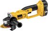
English b. Check to see if receptacle is connected to a light switch which turns power off when you turn out the lights; c. Move charger and battery pack to a location where the surrounding air temperature is approximately 65°F - 75°F (18°- 24°C); d. If charging problems persist, take the tool, battery pack and charger to your local service center. 4. The battery pack should be recharged when it fails to produce sufficient power on jobs which were easily done previously. DO NOT CONTINUE to use under these conditions. Follow the charging procedure. You may also charge a partially used pack whenever you desire with no adverse affect on the battery pack. 5. Under certain conditions, with the charger plugged into the power supply, the exposed charging contacts inside the charger can be shorted by foreign material. Foreign materials of a conductive nature such as, but not limited to, grinding dust, metal chips, steel wool, aluminum foil, or any buildup of metallic particles should be kept away from charger cavities. Always unplug the charger from the power supply when there is no battery pack in the cavity. Unplug charger before attempting to clean. 6. Do not freeze or immerse charger in water or any other liquid. WARNING: Shock hazard. Don't allow any liquid to get inside charger. Electric shock may result. CAUTION: Never attempt to open the battery pack for any reason. If the plastic housing of the battery pack breaks or cracks, return to a service center for recycling. Storage Recommendations 1. The best storage place is one that is cool and dry away from direct sunlight and excess heat or cold. 2. Long storage will not harm the battery pack or charger. Under proper conditions, they can be stored for 5 years or more. SAVE THESE INSTRUCTIONS FOR FUTURE USE FIG. 2 B J A E F C I COMPONENTS (Fig. 2) A. Trigger Switch B. Lock-Off Button C. Spindle Lock Button D. Spindle (not shown) E. Side Handle F. Abrasive Wheel G. Unthreaded Backing Flange (not shown) H. Threaded Clamp Nut (not shown) I. Guard (Type 1, Type 27) J. Battery 12
-
 1
1 -
2
-
3
-
4
-
5
-
6
-
7
-
8
-
 9
9 -
 10
10 -
 11
11 -
 12
12 -
 13
13 -
 14
14 -
 15
15 -
 16
16 -
 17
17 -
 18
18 -
 19
19 -
20
-
21
-
22
-
23
-
24
-
25
-
26
-
27
-
28
-
29
-
30
-
31
-
32
-
33
-
34
-
35
-
36
-
37
-
38
-
39
-
40
-
41
-
42
-
43
-
44
-
45
-
46
-
47
-
48
-
49
-
50
-
51
-
52
-
53
-
54
-
55
-
56
-
57
-
58
-
59
-
60
-
61
-
62
-
63
-
64
-
65
-
66
-
67
-
68
-
69
-
70
-
71
-
72
-
73
-
74
-
75
-
76
-
77
-
78
-
79
-
80
-
81
-
82
-
83
-
84
-
85
-
86
-
87
-
88
 |
 |
