Dewalt DCD985L2 Instruction Manual - Page 11
Variable Speed Trigger Switch Fig. 2, Side Handle Fig. 2, SAVE THESE INSTRUCTIONS, FOR FUTURE USE, - torque
 |
View all Dewalt DCD985L2 manuals
Add to My Manuals
Save this manual to your list of manuals |
Page 11 highlights
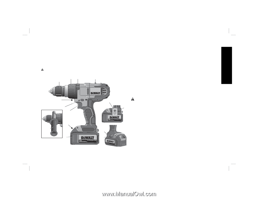
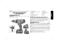
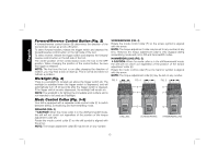
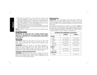
English NOTE: Battery packs should not be stored completely depleted of charge. The battery pack will need to be recharged before use. SAVE THESE INSTRUCTIONS FOR FUTURE USE COMPONENTS (Fig. 2) WARNING: Never modify the power tool or any part of it. Damage or personal injury could result. FIG. 2 EF G D C B A J H I K M L M A. Trigger switch B. Forward/reverse control button C. Worklight D. Chuck E. Torque adjustment collar F. Mode control collar G. Gear shifter H. Side handle I. Battery pack J. Battery release button K. Belt hook L. Bit clip M. Screw Variable Speed Trigger Switch (Fig. 2) To turn the tool on, squeeze the trigger switch (A). To turn the tool off, release the trigger switch. Your tool is equipped with a brake. The chuck will stop as soon as the trigger switch is fully released. NOTE: Continuous use in variable speed range is not recommended. It may damage the switch and should be avoided. Side Handle (Fig. 2) WARNING: To reduce the risk of personal injury, ALWAYS operate the tool with the side handle properly installed. Failure to do so may result in the side handle slipping during tool operation and subsequent loss of control. Hold tool with both hands to maximize control. Side handle (H) clamps to the front of the gear case and may be rotated 360° to permit right- or left-hand use. Side handle must be tightened sufficiently to resist the twisting action of the tool if the accessory binds or stalls. Be sure to grip the side handle at the far end to control the tool during a stall. If model is not equipped with side handle, grip drill with one hand on the handle and one hand on the battery pack. NOTE: Side handle comes equipped on both models. 9
-
 1
1 -
2
-
3
-
4
-
5
-
 6
6 -
 7
7 -
 8
8 -
 9
9 -
 10
10 -
 11
11 -
 12
12 -
 13
13 -
 14
14 -
 15
15 -
 16
16 -
17
-
18
-
19
-
20
-
21
-
22
-
23
-
24
-
25
-
26
-
27
-
28
-
29
-
30
-
31
-
32
-
33
-
34
-
35
-
36
-
37
-
38
-
39
-
40
-
41
-
42
-
43
-
44
-
45
-
46
-
47
-
48
-
49
-
50
-
51
-
52
-
53
-
54
-
55
-
56
 |
 |