Dewalt DW0737 Instruction Manual - Page 1
Dewalt DW0737 Manual
 |
View all Dewalt DW0737 manuals
Add to My Manuals
Save this manual to your list of manuals |
Page 1 highlights
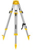
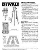
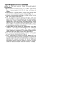
FIG. 1 FIG. 2 FIG. 3 FOOT BRACKET FERRURE DE PATTE SOPORTE DE PIE QUICK ADJUST LATCH VERROU À RÉGLAGE RAPIDE SEGURO DE AJUSTE RÁPIDO FIG. 4 HANDLE FOR 5/8" THREADED SHAFT POIGNÉE DE LA TIGE FILETÉE DE 16 MM (5/8 PO) ASA DEL CILINDRO DE ROSCA DE 5/8" (16 MM) QUICK ADJUST LATCH ASSEMBLY NUT ÉCROU DE L'ENSEMBLE DES VERROUS À RÉGLAGE RAPIDE UERCA DEL CONJUNTO DE SEGURO DE AJUSTE RÁPIDO Heavy-Duty Construction Tripod NOTE: YOUR DEWALT TRIPOD IS FULLY ASSEMBLED 1. Choose a relatively smooth and level surface away from other work site activity to position the tripod. 2. Unlatch the plastic snap at the end of the nylon strap holding the three tripod legs together (Fig. 1). 3. Spread the legs apart to position tripod in upright position with all three feet on the floor or ground (Fig. 2). 4. Use Quick Adjust Latches on all three legs to adjust the tripod to desired height (Fig. 3). Pull up on each latch to release and extend the legs. After the approximate height is set, minor adjustments can be made to bring the Flat Head Mount to level. Before attaching a laser level to the tripod head, check to see that all three legs are wobble free. 5. Ensure that the three Quick Adjust Latches are tight to keep the tripod legs firmly set for safety. If the Quick Adjust Latch is loose in the locked position, tighten the Quick Adjust Latch Assembly Nut (Fig. 4) before proceeding. 6. Use the tripod leg Foot Bracket to press all three feet into soft ground (Fig. 2). 7. To attach a laser level to the head of the tripod, a 5/8" (16 mm) threaded shaft has been provided with a handle for positive grip.Your laser level should have a 5/8" (16 mm) threaded insert in the base to attach to this tripod. Be sure the laser level is tightly held to the tripod head before starting work. Trépied robuste REMARQUE : LE TRÉPIED DEWALT EST COMPLÈTEMENT ASSEMBLÉ. 1. Déposer le trépied sur une surface relativement plane et de niveau, à l'écart de la zone de travaux de chantier. 2. Déverrouiller le fermoir en plastique fixé à l'extrémité de la bande de nylon retenant ensemble les trois pattes du trépied (fig. 1). 3. Étendre les pattes complètement afin d'équilibrer le trépied à la verticale, en s'assurant de bien positionner les trois pattes sur le sol, tel qu'illustré à la figure 2. 4. Régler le trépied à la hauteur voulue au moyen des verrous à réglage rapide situés sur chaque patte (fig. 3); tirer chaque verrou vers le haut pour dégager et allonger les pattes. Une fois la hauteur désirée obtenue, ajuster le trépied afin de mettre la ferrure à tête plate de niveau. Avant de fixer le niveau laser sur la tête du trépied, s'assurer que les trois pattes soient bien stables. 5. Afin de travailler en toute sécurité, s'assurer que les trois verrous à réglage rapide soient bien serrés afin d'éviter que les pattes ne se mettent à bouger. Même s'ils sont verrouillés, les verrous peuvent ne pas être assez serrés; le cas échéant, serrer l'écrou retenant l'ensemble des verrous (fig. 4) avant de procéder. 6. En présence d'un sol mou, utiliser les ferrures des pattes afin d'enfoncer celles-ci dans le sol (fig. 2). 7. Une tige de 16 mm (5/8 po) munie d'une poignée est fournie afin de fixer le niveau laser au trépied (le niveau laser utilisé doit cependant être doté d'une douille filetée de même format pour pouvoir y être fixé). S'assurer que le niveau laser soit solidement fixé au trépied avant de commencer le travail. DEWALT Industrial Tool Co., 701 East Joppa Road, Baltimore, MD 21286 (DEC05) Form No. 638970-00 Copyright © 2001, 2005 DEWALT The following are trademarks for one or more DEWALT power tools: the yellow and black color scheme; the "D" shaped air intake grill; the array of pyramids on the handgrip; the kit box configuration; and the array of lozenge-shaped humps on the surface of the tool.
-
 1
1 -
 2
2
 |
 |