Dewalt DW735X Instruction Manual - Page 6
OPERATION, On/Off Switch, Depth Adjustment, Material Removal Gauge - planer
 |
View all Dewalt DW735X manuals
Add to My Manuals
Save this manual to your list of manuals |
Page 6 highlights
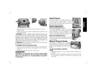
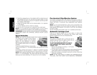
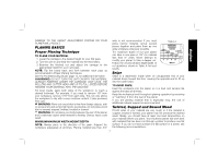
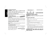
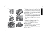
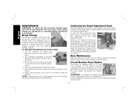
English H I C On/Off Switch K To turn the planer on, lift the switch (L) up. The planer locks on automatically. To turn the tool off, press the switch down. A hole is M provided under the switch (M) for insertion of a padlock to lock off the planer. H L Depth Adjustment 3. Slide the notches in the dust port over the pins on the chip ejection chute. 4. Rotate the port until the button engages the dust ejection chute and locks in place. WARNING: DO NOT OPERATE YOUR PLANER WITHOUT THE DUST EJECTION PORT LOCKED INTO PLACE. DO NOT INSERT ANYTHING INTO THE DUST EJECTION CHUTE UNLESS THE PLANER IS UNPLUGGED AND YOU ARE CLEARING A CLOG OR OBSTRUCTION IN THE UNIT. DO NOT GET YOUR FACE OR EYES NEAR THE DUST EJECTION PORT WHEN THE PLANER IS IN OPERATION. SERIOUS INJURY COULD RESULT. WARNING: Chips are ejected at significant velocity. Keep hands and face clear of dust ejection port. TO REMOVE THE DUST EJECTION PORT 1. Use the T-wrench to depress the lock button on the dust chute. 2. Twist the port until the pins are disengaged from the notches on the port. 3. Pull the dust ejection port off of the dust chute. OPERATION WARNING: To reduce the risk of serious personal injury, turn tool off and disconnect tool from power source before making any adjustments or removing/installing attachments or accessories. DEPTH ADJUSTMENT SCALE The depth adjustment scale (N), located on the right front of your planer, indicates the finished thickness of your workpiece. One rotation of the depth adjustment crank is equal to 1/16", half rotation is equal to 1/32", etc. DEPTH ADJUSTMENT CRANK Turning the crank clockwise lowers the cutter head. Turning the crank counterclockwise raises the cutter head. N Material Removal Gauge Your planer is equipped with a material removal gauge (O). It is used to indicate the amount of wood that will be removed in one pass with the carriage set at its current O height. TO USE THE MATERIAL REMOVAL GAUGE 1. Slide approximately 3" of your material under the middle of the carriage. 2. Be sure the wood is lying flat against the base of the planer. If the material is inserted at an angle, the reading may be inaccurate. 5
-
 1
1 -
 2
2 -
 3
3 -
 4
4 -
 5
5 -
 6
6 -
 7
7 -
 8
8 -
 9
9 -
 10
10 -
 11
11 -
 12
12 -
13
-
14
-
15
-
16
-
17
-
18
-
19
-
20
-
21
-
22
-
23
-
24
-
25
-
26
-
27
-
28
-
29
-
30
-
31
-
32
-
33
-
34
-
35
-
36
-
37
-
38
-
39
-
40
-
41
-
42
-
43
-
44
-
45
-
46
-
47
-
48
-
49
-
50
 |
 |