Dewalt DWE46101 Instruction Manual - Page 14
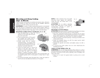
Switches, Mounting and Using Depressed Center, Grinding Wheels and Sanding Flap Discs
 |
View all Dewalt DWE46101 manuals
Add to My Manuals
Save this manual to your list of manuals |
Page 14 highlights
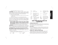
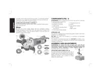
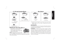
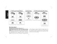
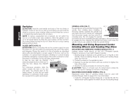
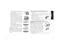
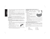
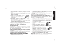
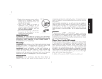
English Switches CAUTION: Hold the side handle and body of the tool firmly to maintain control of the tool at start up and during use and until the wheel or accessory stops rotating. Make sure the wheel has come to a complete stop before laying the tool down. NOTE: To reduce unexpected tool movement, do not switch the tool on or off while under load conditions. Allow the grinder to run up to full speed before touching the work surface. Lift the tool from the surface before turning the tool off. Allow the tool to stop rotating before putting it down. SLIDER SWITCH (FIG. 6) CAUTION: Before connecting the tool to a power supply, be sure the switch is in the off position by pressing the rear part of the switch and releasing. Ensure the switch is in the off position as described above after any interruption in power supply to the tool, such as the activation of a ground fault interrupter, throwing of a circuit breaker, accidental unplugging, or power failure. If the switch is locked on when the power is connected, the tool will start unexpectedly. To start the tool, slide the ON/OFF FIG. 6 switch (I) toward the front of the tool. To I stop the tool, release the ON/OFF switch. For continuous operation, slide the switch toward the front of the tool and press the forward part of the switch inward. To stop the tool while operating in continuous mode, press the rear part of the switch and release. SPINDLE LOCK (FIG. 7) FIG. 7 The spindle lock (A) is provided to prevent the spindle from rotating when installing or removing wheels. Operate the spindle lock A only when the tool is turned off, unplugged from the power supply, and has come to a complete stop. Do not engage the spindle lock while the tool is operating because damage to the tool will result. To engage the lock, depress the spindle lock button and rotate the spindle until you are unable to rotate the spindle further. Mounting and Using Depressed Center Grinding Wheels and Sanding Flap Discs MOUNTING AND REMOVING HUBBED WHEELS (FIG. 1) Hubbed wheels install directly on the 5/8"-11threaded spindle. Thread of accessory must match thread of spindle. 1. Backing flange is retained to the grinder by an O-ring (N) on the spindle. Remove backing flange by pulling and twisting flange away from the tool. 2. Thread the wheel on the spindle by hand. 3. Depress the spindle lock button and use a wrench to tighten the hub of the wheel. 4. Reverse the above procedure to remove the wheel. CAUTION: Failure to properly seat the wheel before turning the tool on may result in damage to the tool or the wheel. MOUNTING NON-HUBBED WHEELS (FIG. 8) Depressed center Type 27 grinding wheels must be used with included flanges. Refer to page 9 for more information. 1. Install the unthreaded backing flange (E) on spindle (B) with the raised section (pilot) against the wheel. Be sure the backing flange 12
-
 1
1 -
2
-
3
-
4
-
5
-
6
-
7
-
8
-
 9
9 -
 10
10 -
 11
11 -
 12
12 -
 13
13 -
 14
14 -
 15
15 -
 16
16 -
 17
17 -
 18
18 -
 19
19 -
20
-
21
-
22
-
23
-
24
-
25
-
26
-
27
-
28
-
29
-
30
-
31
-
32
-
33
-
34
-
35
-
36
-
37
-
38
-
39
-
40
-
41
-
42
-
43
-
44
-
45
-
46
-
47
-
48
-
49
-
50
-
51
-
52
-
53
-
54
-
55
-
56
-
57
-
58
-
59
-
60
-
61
-
62
-
63
-
64
-
65
-
66
 |
 |