EVGA 113-YW-E115-TR Visual Guide
EVGA 113-YW-E115-TR Manual
 |
View all EVGA 113-YW-E115-TR manuals
Add to My Manuals
Save this manual to your list of manuals |
EVGA 113-YW-E115-TR manual content summary:
- EVGA 113-YW-E115-TR | Visual Guide - Page 1
C V 3 n. Intelligent Innovation EVGA nForce 730i Visual Guide a. b. c. The following quick steps will guide you through testing the absolute bare minimum essentials of your motherboard before installing it into a system chassis. Visual aids are provided to assist you during the following - EVGA 113-YW-E115-TR | Visual Guide - Page 2
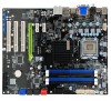
w3A . Intelligent Innovation EVGA nForce 730i Quick Install Guide Install the CPU 1. Unlock the socket by motherboard has one PCI Express X16 slot for a discrete graphics card or you can choose to use the onboard graphics processor for video output. LA-T..353 MPCIEJI1_2 Alt 113-YW-E115
-
 1
1 -
 2
2
 |
 |

a.
C
V
3
n.
Intelligent
Innovation
EVGA
nForce
730i
Visual
Guide
b.
c.
The
following
quick
steps
will
guide
you
through
testing
the
absolute
bare
minimum
essentials
of
your
motherboard
before
installing
it
into
a
system
chassis.
Visual
aids
are
provided
to
assist
you
during
the
following
procedures.
To
reduce
the
risk
of
fire,
electric
shock,
and
injury
always
follow
basic
safety
precautions.
It
is
recommended
that
you
use
electrostatic
discharge
(ESD)
countermeasures
such
as
an
ESD
wrist
strap
or
anti
-static
mat
when
handling
computer
components.
After
removing
the
EVGA
nForce
730i
from
its
packaging,
place
it
on
to
a
nonconductive
surface.
For
example:
wood,
cardboard
box,
or
an
anti
-static
mat.
Unhook
the
socket
lever
and
lift
up
the
load
plate.
Remove
the
LGA
775
protective
cover
and
carefully
install
your
Intel
processor
making
sure
to
properly
align
the
notches.
Close
the
load
plate
and
with
light
pressure,
lower
the
socket
lever
back
in
to
its
original
position.
•
a.
a.
b.
II
Plug
in
one
keyboard
into
a
USB
port
or
PS/2
port.
,•
II
o
e
e
e
b.
9
•
•
I
„
'WI
WM
MI
. •
.
Lai
.
•
.
z'i
:••
'
.
1:::
-
111111111.11.1
'
(TM"
-
swo
a
a
•••
•
f •
•
••
•Fl."
•
Oil
I • •
•
-
•1
11.1•3
..1
s
Ts
ts
.f
te
s,
S
,
•
'3
•
CI
•04
-
,
•
I • •
•
'•1410
"1
1i.
•
•
111306
Op
•
a.
•
•••
••••
Oa
it.;
8
An.
••••
•••
air
‘,..•
it
.
flu
.1•6
••
I
•••••••••••
66.
•
•
•
•
••••••••••
6660
VVVVVV
•••=
•••••••••••••
••••••••,•,••••
:••••••••••
••••••••
I•••••••••
I••••••
111•••••••••
"O.
1••••••••I
-
••••••••••••••le.
4
.-
-
1•06
r.
p
1
/
4
.1.i.
.1;
I.
31
".
1
k
al*
pTt
•
Insert
your
graphics
card
into
either
the
PCI-E
2.0
slot
or
the
PCI
slot.
The
type
of
slot
depends
on
the
graphic
card
i3444
bus
type.
Connect
a
monitor
to
the
output
connector
of
the
graphics
card.
r
•
c.
a.
o
0
0
d.
b.
O
0
Plug
in
power
connectors
to
both
the
graphics
card
and
the
hard
disk
drive.
Power
connector
types
will
vary
depending
on
the
hard
disk
drive
and
graphic
card's
power
requirements.
.'s
MA
4
•••
O
361
eg
41
N
-
2
355555
1;•15
5
212ir
I
co
swim
5f6D5Li
i
try
AM
cw
i
•
•
<se
J
.2
1
1
re
L
BC=
1.11
II.'
.41
1
•
,
•1.•1
•
'Ill=
.
,•
1
•
•017
13
3
Cie
Sas
C106
COI
Chit
PI
0111
•
•
1111.1
6117
NM
IMO
5108
•
R
.
101
NISI
OM
6110
•
JT/1/8
111911••••
•
It
r
,
•
cw
AIM
YI
OM
5130
PPM.)
VIP
nes
001
Cts.
UM Ilia
CM
ATV
NM AM
WM
Mr
NM NM
NM 060
E
Sill
I
Ni.
I I
II
Atli;
III!
311-
I
! " I
.91
CISO
C160
3163
6130
SUM
C1111
1131
CIS1
•
133
142
PCIC_Xl_2
031MILT
411.0.
ON
011
533
es
1•11
.011
CM°
6100
§
Silo
•
N
3104
1111•611
I
31
4
113-1114113
331
33,
ue
•
rs
•
•
s3
gg
DD
is UN
'a
a.'
0/
WO
0 .
NMI
CM
C.I.
e•VC
"
7.
A
3
7111PU
V
li
VV
"
WC
r
.....
,•
kw.*
•
0.
KC
1.•te•••••••
ICl/
Lo
"
PCI
',II
,
•
fi
Ol
a
Ai
-
—
666
•••
•••
$cis
PCI
5101
#
111
O
s'
•
$
1
%
lcatir
MID
Tea
*were
TM*.
lb
•
WWWWWWWW•wWWWWWW••••••Www•••••••wwwwww•••••••••••••••
11111.111II•111011•11.1
.
e';
,tits
.
tines
•
puled
•
s
4
•
In
)
,
•
3.130
••••
•••
11
s.
•14
3
4
F.
Nit
b.
c.
Apply
a
small,
pea
-sized
drop
of
thermal
paste
on
to
the
middle
of
the
processor.
Install
your
processor
heatsink
and
fan.
••••01
,
011
..
3
,
111
7;;;;
I
).
•
r.
•
•
••
•
-
•
-
1
•
3
•
•
41411IT
Clab
3831333
a.
©
©
0
0
b.
Press
the
onboard
Clear
CMOS
button
Press
the
red
Power
Button
On
the
power
supply,
flip
the
power
switch
to
the
ON
position.
LEDs
will
now
be
lit
on
the
motherboard.
Press
the
onboard
Clear
CMOS
button
once
then
press
the
red
Power
Button
to
begin
powering
up
the
system.
At
this
final
stage,
you
should
now
be
greeted
with
the
POST
screen
on
your
monitor.
•
11.
3
C.30/11
00
tart
"
a
00
b.
1
? '
—
.I.•
.......
iriii
:I
t
I.
L
I:..
t.
h
i
t
p
i
.11
IIIIi
4
;v"-,,,
0,
41
0
'
of
ii
Install
one
stick
of
system
memory
(DIMM)
in
to
the
DIMM
slot
of
your
choice.
41,
1
P
.0
)
a.
C.
d.
b.
Make
sure
your
power
supply's
power
switch
is
in
the
OFF
position
then
connect
your
24
-Pin
ATX
Power
Connector
and
8
-Pin
CPU
Power
Connector
to
the
motherboard.
•
a.
c.
t
l
IP
_
A
lb
,
SATA
Connection
o
4
--41-41
2)ilt
I
to,
‘,-
-
4%7t
,
§%i
i
b.
IDE
Connection
d.
Connect
one
hard
drive
disk
to
either
one
of
the
SATA
Connectors
or
to
the
IDE
Connector
depending
on
the
hard
disk
drive
connection
type.