EVGA 113-YW-E115-TR Visual Guide - Page 2
cffli
 |
View all EVGA 113-YW-E115-TR manuals
Add to My Manuals
Save this manual to your list of manuals |
Page 2 highlights
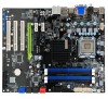
w3A . Intelligent Innovation EVGA nForce 730i Quick Install Guide Install the CPU 1. Unlock the socket by pressing the lever sideways, then lift it up to a 90° angle. 2. Lift the load plate. There is a protective socket cover on the load plate to protect the socket when there is no CPU installed. 3. Remove the protective socket cover from the load plate. (Save this protective piece, as it is needed whenever transporting or shipping the motherboard.) 4. Align the notches in the CPU with the notches on the socket. 5. Lower the CPU straight into the socket. Close the lid plate and engage the socket lever. 6. The CPU will need a proper cooling solution, please refer to the manual that came with your heatsink for detailed instructions. 4 PSG Install System Memory (DIMMs) 1. This motherboard supports up to four 240-pin DDR2 memory modules. Having matched pairs is highly recommended for dual channel configurations. 2. For dual channel configurations use DIMM slots 1 and 2, 3 and 4, or 1 through 4. It is recomended to use the "Black Slots" if running in 2 Dimm Mode * Use matching color slots for dual channel Install Graphics Card 1. This motherboard has one PCI Express X16 slot for a discrete graphics card or you can choose to use the onboard graphics processor for video output. LA-T..353 MPCIEJI1_2 Alt 113-YW-E115 CV3A tan umuguingliim lllllllllll lllll • llllllllllllllll llllllllllllllllll I lllll II llllllllllllllllllll lllllll III• MOM iii• "' PCIE_XIA llll 1.1126 0. GPU 1 llllllllll I llllllllllllllllll PCI SLOT z it llllll III 111,1111111111111111111111111111111 CI PCI Express X16 slot Connect Peripherals 1. Connect your peripheral devices such as hard drives, • floppy drive, and DVD-ROM drives to the motherboard. Cables Please see the manual for more details : Milan 111F11111 8 pin 12v power 24 pin Ai X power Floppy (I) IDE w SATA For package information and more details, please visit the manual. 2. Connect power cables to the motherboard and any other peripherals in your system. * Remember to plug in your PCI-E power cables to your graphics card(s) if necessary. 3. Connect the front panel headers and any other headers that are going to be in use. 2 35 7 8 R Ai k 1. PS/2 Mouse Port 2. PS/2 Keyboard Port 3. HDMI Port 4. Coaxial SPDIF output 5. Optical SPDIF output 6. VGA Port 7. DVI-D Port 8. USB 2.0 Ports 9. LAN Port 10. Audio Port Connector Front Audio Connector 9 7531 0 0 0 0 0 O O0 0 10 8 6 4 2 Pin Signal 1 PORT1_L 2 AUD_GND 3 PORT1_R 4 PRECENCE J 5 PORT2_R 6 SENSE1 RETURN 7 SENSE_SEND 8 Empty 9 PORT2_L 10 SENSE2_RETURN 00100 0000 C IP( II wl urn IIPS1 ll 11 11 r•l=•1:63" 9119,, Ram a 111..1•15 I ev3A: 6 tf ,Tyry,1. NT' 10 111I110 c sum pm" O Floppy Channel Connector SPDIF 2 4 6 0- 10 - 1< - 1 • • • 1 • C) 3 5 Pin Definition 1 Power 2 No Pin 3 SPDIF 4 SPDIFI 5 GROUND 6 GROUND Connector USB 2.0 Header Connector 135 79 I k I£ £ 2 4 6 8 10 Pin Signal Pin Signal 1 5V_DUAL 2 5V DUAL 3 D- 4 D- 5 D+ 6 D+ 7 GND 8 GND 9 Empty 10 No Connect IDE Channel SATA ports fro• Blank 10 9 No Connect g0ocff00li _ PWRSW RESET PWRLEI HDLED 00 + 2 1 Connector Speaker Header 4 0 3 0 2 0 Pin Signal 1 VCC 2 Empty 3 GND 4 Speaker A® Zo V J Premium Services Advanced RMA Stepping-Up Your Customer Service 9ODaY Step-Up" Program 1+1 Warranty www.evga.com/warranty/ A® Om% ft I 0'1 vV Support 24/7 Support 888 • 881. EVGA *27/7 North America only www.evga.com/24-7 Thank you for purchasing an EVGA product. Please remember to register your product at: www.evga.com/register For the latest drivers and updates for your product please visit: www.evga.com/support/drivers To visit and search our knowledge base and product FAQ please visit: www.evga.com/FAQ To visit the EVGA community message boards please visit: forums.evga.com For more information about these services as well as our terms and conditions please visit www.evga.com EVGA Corp. 2900 Saturn Street, Suite B Brea, CA 92821
-
 1
1 -
 2
2
 |
 |
