EVGA 121-LF-E652-KR User Guide
EVGA 121-LF-E652-KR - P55 Micro Motherboard Manual
 |
UPC - 843368011680
View all EVGA 121-LF-E652-KR manuals
Add to My Manuals
Save this manual to your list of manuals |
EVGA 121-LF-E652-KR manual content summary:
- EVGA 121-LF-E652-KR | User Guide - Page 1
User's Guide EVGA P55 Micro Motherboard - EVGA 121-LF-E652-KR | User Guide - Page 2
- EVGA 121-LF-E652-KR | User Guide - Page 3
Contents User's Guide ...1 EVGA P55 Micro Motherboard...1 Before You Begin...7 Before You Begin...7 Parts NOT in the Kit ...7 EVGA P55 Micro Motherboard ...8 Motherboard Specifications...8 Hardware Installation ...10 Safety Instructions ...10 Preparing the Motherboard ...11 Installing the CPU ...11 - EVGA 121-LF-E652-KR | User Guide - Page 4
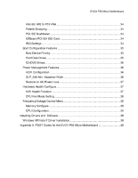
...22 PCI Express x1 Slots ...22 PCI Express x16/x8/x4 Slots ...22 Onboard Buttons ...23 Clear CMOS Button ...23 Post Port Debug LED and LED Status Indicators ...24 Post Port Debug LED ...24 LED Status Indicators ...24 Configuring the BIOS ...25 Enter BIOS Setup ...26 Main Menu...26 Standard BIOS - EVGA 121-LF-E652-KR | User Guide - Page 5
Configure...37 H/W Health Function ...37 CPU Fan Mode Setting ...38 Frequency/Voltage Control Menu ...38 Memory Configure ...38 CPU Configuration ...38 Installing Drivers and Software ...39 Windows XP/Vista/7 Driver Installation ...39 Appendix A. POST Codes for the EVGA P55 Micro Motherboard ...40 - EVGA 121-LF-E652-KR | User Guide - Page 6
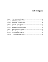
4. Figure 5. Figure 6. Figure 7. Figure 8. Figure 9. Figure 10. PW1 Motherboard Connector ...16 CMOS Setup Utility Main Menu ...27 Standard BIOS Features Menu ...28 Advanced BIOS Features ...30 Advanced Chipset Features ...31 PCI/PNP Resource Management ...33 Boot Configuration Features ...35 Power - EVGA 121-LF-E652-KR | User Guide - Page 7
new EVGA P55 Micro Motherboard. However, it does not contain the following items that must be purchased separately to make the motherboard functional. Intel Socket 1156 Processor DDR3 System Memory Socket 1156 or Socket 775 Cooling fan PCI Express or PCI Graphics Card Power Supply EVGA assumes - EVGA 121-LF-E652-KR | User Guide - Page 8
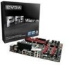
EVGA P55 Micro Motherboard Motherboard Specifications Size ATX form factor of 9.6 inch x 9.6 inch Processor support Intel Socket 1156 CPU's Operating systems: Supports Windows XP 32bit/64bit, Windows Vista 32bit/64bit, and Windows 7 32bit/64bit Intel P55 Express Chipset System Memory - EVGA 121-LF-E652-KR | User Guide - Page 9
and Power Interface) Supports S0 (normal), S1 (power on suspend), S3 (suspend to RAM), S4 (Suspend to disk - depends on OS), and S5 (soft - off) Expansion Slots One PCI slots One PCI Express x1 slot Two PCI Express x8 slots e-SATA Two e-SATA ports at rear panel 300MBps data transfer rate - EVGA 121-LF-E652-KR | User Guide - Page 10
Installation This section will guide you through the installation of the motherboard. The topics covered in this section are: Preparing the motherboard Installing the CPU Installing the CPU fan Installing the memory Installing the motherboard Connecting cables Safety Instructions To reduce the - EVGA 121-LF-E652-KR | User Guide - Page 11
the following procedure to install the CPU onto the motherboard: Unhook the socket lever by pushing down and away from the socket. Pull the socket lever back and the load plate will automatically lift. There is a protective socket cover within the CPU socket to protect the socket when there is no - EVGA 121-LF-E652-KR | User Guide - Page 12
lever. Align notches with notches on the CPU Load plate tip under screw cap Installing the CPU Fan There are many different fan types that can be used with this motherboard. Follow the instruction that came with you fan assembly. Be sure that the fan orientation is correct for your chassis type - EVGA 121-LF-E652-KR | User Guide - Page 13
Installing System Memory (DIMMs) Your new motherboard has four 240-pin slots for DDR3 memory. These slots support 1GB, 2GB, 4GB DDR3 technologies. There must be at least one memory bank populated to ensure normal operation. Use the following the recommendations for installing - EVGA 121-LF-E652-KR | User Guide - Page 14
comes with an I/O shield that is used to block radio frequency transmissions, protects internal components from dust and foreign objects, and promotes correct airflow within the chassis. Before installing the motherboard, install the I/O shield from the inside of the chassis. Press the I/O shield - EVGA 121-LF-E652-KR | User Guide - Page 15
to the fan assembly instruction. Secure the motherboard with a recommended minimum of nine (9) screws. 2. 3. 4. 5. Connecting Cables This section takes you through all the necessary connections on the motherboard. This will include: Power Connections 24-pin ATX power (PW1) 8-pin ATX 12V power - EVGA 121-LF-E652-KR | User Guide - Page 16
, the 8-pin ATX 12V power connection, is used to provide power to the CPU. Align the pins to the connector and press firmly until seated. Connecting Serial ATA Cables The Serial ATA II connector is used to connect the Serial ATA II device to the motherboard. These connectors support the thin Serial - EVGA 121-LF-E652-KR | User Guide - Page 17
II interface allows up to 300MB/s data transfer rate. There are six (6) internal serial ATA connectors on this motherboard. These connections are designed to be angled to not interfere with any expansions cards. These connection points support RAID 0, RAID 1, and RAID 10 configurations. SATA 5 (top - EVGA 121-LF-E652-KR | User Guide - Page 18
Connecting Internal Headers Front Panel Header The front panel header on this motherboard is one connector used to connect the following four cables. (see Table 2 for pin definitions): PWRLED Attach the front panel power LED cable to these two pins of the connector. The Power LED indicates the - EVGA 121-LF-E652-KR | User Guide - Page 19
system case (not all system cases are equipped with the front panel option). Connect the end of the cable to the IEEE1394a header on the motherboard. Table 3. Connector IEEE 1394a Connector Pins Pin 1 2 3 4 5 6 7 8 9 10 Signal TPA+ TPAGND GND TPB+ TPB+12V +12V Empty GND IEEE 1394a Connector 10 - EVGA 121-LF-E652-KR | User Guide - Page 20
(not all chassis are equipped with the front panel option). Connect the end of the cable(s) to the USB 2.0 header on the motherboard. 2. Table 4. USB 2.0 Header Pins Connector USB 2.0 Header Connector Pin 1 3 5 7 9 Pin 2 4 6 8 10 Signal 5V_DUAL DD+ GND Empty Signal 5V_DUAL DD+ GND No Connect - EVGA 121-LF-E652-KR | User Guide - Page 21
Audio The audio connector supports HD audio standard and provides two kinds of audio output choices: the Front Audio, the Rear Audio. The front Audio supports re-tasking function. Table 5. Connector Front Audio Connector Pin 1 2 3 4 5 6 7 8 9 10 Signal PORT1_L AUD_GND PORT1_R PRECENCE_J PORT2_R - EVGA 121-LF-E652-KR | User Guide - Page 22
x1 cards, such as an EVGA Killer Xeno Network Card or Sound Card. The x1 slot provides 250 MB/sec bandwidth. PCI Express x16/x8/x4 Slots These PCI Express slots are reserved for Graphic Cards and PCI Express x1 and x4 devices. The design of this motherboard supports multiple Graphic Card technology - EVGA 121-LF-E652-KR | User Guide - Page 23
and Clear CMOS. These functions allow you to easily reset the system, turn on/off the system, or clear the CMOS. Clear CMOS Button The motherboard uses the CMOS RAM to store all the set parameters. The CMOS can be cleared by pressing the Clear CMOS button either onboard or on - EVGA 121-LF-E652-KR | User Guide - Page 24
is useful during troubleshooting situations. This Debug LED will also display current CPU temperatures after the system System. Debug LED with CPU Temperature Monitor LED Status Indicators The LEDs near the 24pin ATX connector indicate the system's motherboard is receiving constant power. - EVGA 121-LF-E652-KR | User Guide - Page 25
are also provided. This section includes the following information: Enter BIOS Setup Main Menu Standard BIOS Features Advanced BIOS Features Advanced Chipset Features PCI/PnP Resource Management Boot Configuration Features Power Management Features Hardware Health Configure Frequency/Voltage - EVGA 121-LF-E652-KR | User Guide - Page 26
previous menu, press Esc. CMOS Setup Utility - Copyright (C) 1985-2005, American Megatrends Standard BIOS Features Advanced BIOS Features Advanced Chipset Features PCI/PNP Resource Management Boot Configuration Features Power Management Features Hardware Health Configure Frequency - EVGA 121-LF-E652-KR | User Guide - Page 27
Figure 2. CMOS Setup Utility Main Menu Standard BIOS Features Use this menu to set up the basic set up onboard peripherals such as IDE, RAID, USB, LAN, and MAC control. PCI/PNP Resource Management Use this menu to configure resource management. Boot Configuration Features Use this - EVGA 121-LF-E652-KR | User Guide - Page 28
menu, press Esc. CMOS Setup Utility - Copyright (C) 1985-2005, American Megatrends Standard BIOS Features System Overview _____ AMIBIOS Version :08.00.16 Build Date:07/16/10 ID :1E655000 Processor Intel(R) Core(TM) CPU Speed :2666MHz Count :1 System Memory Size :4088MB System Time System Date Move - EVGA 121-LF-E652-KR | User Guide - Page 29
Configuring the BIOS System Time / System Date Using the arrow keys, position the cursor over the month, day, and year. Use the + and - keys to scroll through dates and times. Note that the weekday (Sun through Sat) cannot be changed. This field changes to correspond to the date you enter. Note - EVGA 121-LF-E652-KR | User Guide - Page 30
Advanced Settings _____ WARNING: Setting wrong values in below sections may cause system to malfunction IDE Configuration [Press Boot Settings Configuration[Press AHCI Configuration [Press USB Configuration [Press Enter] Enter] Enter] Enter] Help Item Main Level Select Removable Boot Device - EVGA 121-LF-E652-KR | User Guide - Page 31
to enable Legacy USB support, force USB 1.1 mode Bridge Configuration [Press Enter] PCI Express Configuration [Press Enter] Intel VT-d [Disabled] HD Audio Controller [Enabled] IEEE1394 [Enabled] LAN Controller [Enabled] LAN Boot [Disabled] PE1 Slot [Auto] P80 Show CPU - EVGA 121-LF-E652-KR | User Guide - Page 32
you to set advanced PCI Express options, such as Payload size. It is not recommended to adjust these settings. Intel VT-d Configuration This , such as an EVGA Killer Xeno card. PE1 Slot This function allows you to enable or disable the PE1 Slot. P80 Show CPU Temperature When this function - EVGA 121-LF-E652-KR | User Guide - Page 33
_____ WARNING: Setting wrong values in below sections may cause system to malfunction. Clear NVRAM Plug & Play O/S PCI Latency Timer Allocate IRQ to PCI VGA Palette Snooping PCI IDE BusMaster OffBoard PCI/ISA IDE Card IRQ3 IRQ4 IRQ5 IRQ7 IRQ9 IRQ10 Move Enter:Select F5:Previous Values [No] [No] [64 - EVGA 121-LF-E652-KR | User Guide - Page 34
to inform the system that an ISA graphics device is installed. PCI IDE BusMaster This function allows the BIOS to use PCI BusMastering for reading or writing to IDE drives. OffBoard PCI/ISA IDE Card This function allows manual override of PCI/ISA external cards. A setting of [Auto] works for most - EVGA 121-LF-E652-KR | User Guide - Page 35
F1:General Help F5:Previous Values F6:Fail-Safe Defaults F7:Optimized Defaults Figure 7. Boot Configuration Features Boot Device Priority This option menu will allow specification of the boot device priority sequence. Hard Disk Drives This option menu allows you - EVGA 121-LF-E652-KR | User Guide - Page 36
CD/DVD Drives This option menu allows you specification of the CD/DVD boot priority sequence. Power Management Features Select Power Management Features from the CMOS Setup Utility menu and press Enter to display - EVGA 121-LF-E652-KR | User Guide - Page 37
press Enter to display the settings. Hardware Health Configure H/W Health Function [Enabled] _____ CPU Temperature Sensor VREG Temperature Sensor System Temperature Sensor CPU Fan Speed Power Fan Speed Chassis Fan Speed VCore Memory CPU VTT PCH +5V :34C/93F :48C/118F :34C/93F :3264 RPM :1337 RPM - EVGA 121-LF-E652-KR | User Guide - Page 38
Frequency Setting PCIE Frequency Setting [Press Enter] [Press Enter] [20] [133] [100] Item Help Main Level EVGA VDroop Control [With VDroop] Current CPU VCore : 1.33700V CPU VCore [Auto] Current Dimm Voltage : 1.50V DIMM Voltage [Auto] Current VTT : 1.050V VTT [Auto] Current PCH Voltage : 1.050V - EVGA 121-LF-E652-KR | User Guide - Page 39
shipped with the EVGA P55 Micro Motherboard contains the following software and drivers: Chipset Drivers Audio drivers LAN Drivers RAID Drivers EVGA E-LEET Overclocking Utility Adobe Acrobat Reader User's Manual Windows XP/Vista/7 Driver Installation 5. 6. Insert the Intel P55 installation CD - EVGA 121-LF-E652-KR | User Guide - Page 40
section provides the AMI POST Codes (Table 6) for the EVGA P55 Micro Motherboard during system boot up. The POST Codes are displayed on the Debug LED readout located directly onboard the motherboard. This Debug LED will also display current CPU temperatures after the system has fully booted into the - EVGA 121-LF-E652-KR | User Guide - Page 41
Configuring the BIOS Code Description 20 24 2A 2C 2E 31 33 37 38 39 3A 3B 3C 40 52 60 75 78 7C 84 85 87 8C 8D 8E 90 A1 A2 A4 A7 A9 Relocate System Management interrupt vector Uncompress and initialize BIOS module Initialize devices primary Initialize devices secondary Initialize output devices - EVGA 121-LF-E652-KR | User Guide - Page 42
Save system context for ACPI Pass control to OS Show CPU Temp (if enabled) EVGA Glossary of Terms ACPI - Advanced Configuration and Power Complementary Metal-Oxide Semiconductor CPU - Central Processing Unit D-ICE - Dry Ice Cooling DDR2 - Double Data Rate 2 DDR3 - Double Data Rate 3 DIMM - Dual - EVGA 121-LF-E652-KR | User Guide - Page 43
Definition Multimedia Interface HDR - High Dynamic Range Lighting HPET - High Precision Event Timer HT - Hyper-Threading HSF - Heat Sink Fan Network LCD - Liquid Crystal Display LGA - Land Grid Array LN2 - PCI - Peripheral Component Interconnect PCIe - Peripheral Component Interconnect Express PCI - EVGA 121-LF-E652-KR | User Guide - Page 44
QDR - Quad Data Rate QPI - Quick Path Interconnect RAID - Redundant Array of Inexpensive Disks RGB - Red Green Blue SATA - Serial Advanced Technology Attachment SB - Southbridge SCSI - Small Computer System
-
 1
1 -
 2
2 -
 3
3 -
 4
4 -
 5
5 -
 6
6 -
 7
7 -
8
-
9
-
10
-
11
-
12
-
13
-
14
-
15
-
16
-
17
-
18
-
19
-
20
-
21
-
22
-
23
-
24
-
25
-
26
-
27
-
28
-
29
-
30
-
31
-
32
-
33
-
34
-
35
-
36
-
37
-
38
-
39
-
40
-
41
-
42
-
43
-
44
 |
 |

User
’s
Guide
EVGA P55 Micro Motherboard