EVGA 123-LF-E653-KR Visual Guide - Page 1
EVGA 123-LF-E653-KR - P55 LE Motherboard Manual
 |
UPC - 843368011697
View all EVGA 123-LF-E653-KR manuals
Add to My Manuals
Save this manual to your list of manuals |
Page 1 highlights
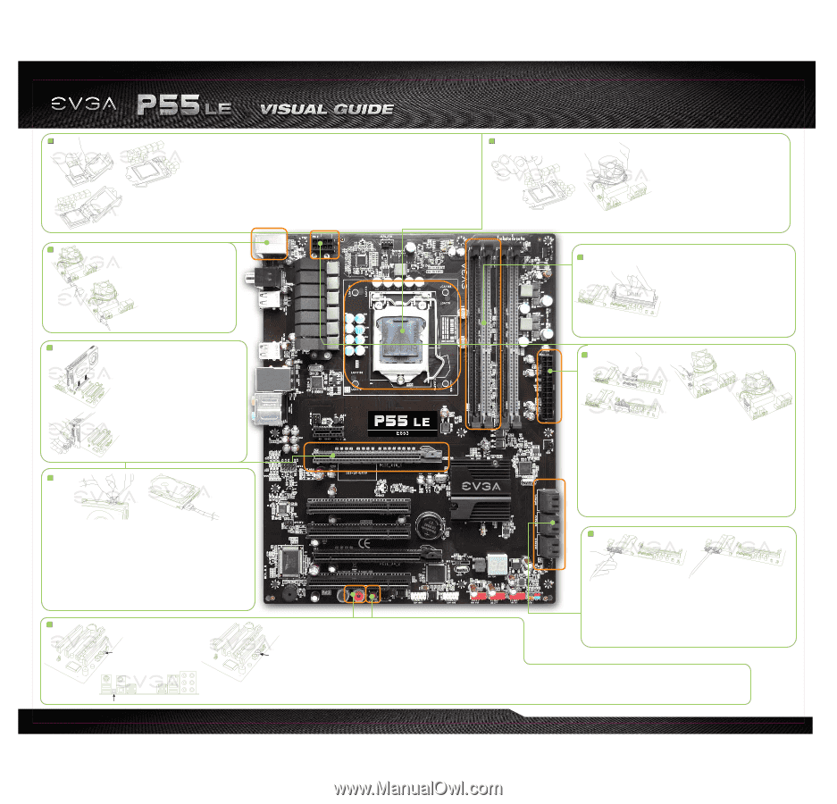
1 a. b. 3 a. b. • Pull the socket lever back and the load plate will automatically lift. • Ziehen Sie den Hebel nach hinten, und die Halterung öffnet sich automatisch. c. • Remove the protective socket cover from the CPU Socket in a straight up motion. • Align the notches in the processor with the notches on the socket. • Entfernen Sie die Schutzabdeckung vom CPU-Sockel, indem Sie ihn nach oben abheben. • Bringen Sie die Einkerbungen der CPU mit denen des CPU-Sockels in Übereinstimmung. 2 • Lower the processor straight down into the socket without tilting or sliding it into the socket. • Legen Sie die CPU in einer geraden Abwärtsbewegung in den Sockel, ohne sie zu verkanten oder • Lower the load plate so it is resting on the CPU. • Pull back the socket lever again to ensure the load plate tip engages under the shoulder screw cap. • Carefully close and latch the lever. seitwärts zu verschieben. • Klappen Sie die Halterung zurück, sodass sie auf der CPU liegt. • Ziehen Sie den Hebel der Sockelverriegelung zurück, um sicher zu stellen, dass sich die Zungen der a. CPU V CPU Halterung unter dem Kopf der Zapfenschraube befinden. • Verriegeln Sie den Hebel wieder. CPU Socket CPU • Soulevez le levier en le poussant vers le bas et le rabat métallique se soulèvera. • Enlevez le couvercle protectif du socket du CPU en le soulevant verticalement. • Alignez les détrompeurs du processeur avec les détrompeurs du socket. • Abaissez le processeur verticalement dans le socket sans l'incliner dans le socket. • Abaissez le rabat métallique pour qu'il se repose sur le CPU. • Replacez le levier du socket en position et assurez-vous que le rabat métallique soit sécurisé sous la vis. • Fermez et verrouillez avec précaution le levier. CPU CPU • Mueva hacia atrás la palanca del conector y el plato de carga (load plate) automáticamente levantara. • Quite el cubierto protectora del socket del CPU en posición hacia arriba. • Alinee las muescas (notches) en el procesador con las muescas en el socket. • Baje el procesador al socket sin deslizarlo del socket. • Baje el plato de carga para y deber de estar apoyándose en el CPU. • Mueva hacia atrás la palanca del socket otra vez para asegurar que el plato de carga este debajo del tornillo. • Cierre cuidadosamente la palanca. Plug in one keyboard into a USB port or PS/2 port USBϙʔτ·ͨPS/2 Branchez un clavier dans un port USB ou PS/2. Enchufar el teclado al puerto USB o PS/2. Schließen Sie die Tastatur am USB- oder PS/2-Port an USB接頭或PS/2 USB接口或PS/2接口。 b. 4 a. PN #: 132-LF-E653-KR Apply a small, pea-sized drop of thermal paste on to the middle of the processor. Install your processor heatsink and fan Appliquez une petite noisette de pâte thermique sur le milieu du processeur. Installez votre Ventirad (Radiateur et Ventilateur). Aplíquele una cantidad pequeña, de pasta termal en el centro del procesador. Instale su disipador del procesador y su ventilador. Geben Sie einen erbsengroßen Tropfen Wärmeleitpaste mittig auf die CPU. Installieren Sie Ihren CPU-Lüfter Install DIMMs into the appropriate DIMM slots (see other side). DIMMΛదͳDIMM Installez les barrettes de mémoire dans les ports appropriés DIMM. Instale los DIMMs en las ranuras apropiadas (ver lado contrario) DIMM. Stecken Sie die DIMM-Module in die dafür vorgesehenen Steckplätze 5 Insert your graphics card into either the PCI-E 2.0 slot or the PCI slot. The type of slot depends on the graphic card bus type. Connect a monitor a. to the output connector of the graphics card. PCI-E 2.0 PCI Installez votre carte graphique dans un port PCI-E 2.0 ou PCI. Le type d'emplacement dépend de la carte graphique utilisée. Connectez un écran au connecteur de la carte graphique. Inserte su tarjeta gráfica en la ranura PCI-E 2.0 o la ranura PCI. El tipo de ranura depende del tipo de tarjeta gráfica. Conecte el monitor para el conector de salida de la tarjeta gráficos. b. Stecken Sie Ihre Grafikkarte in den PCI-E-2.0- oder PCI-Steckplatz. Der Steckplatz hängt vom Bus Ihrer Grafikkarte ab. Verbinden Sie Ihren Bildschirm mit dem Anschluss an der Grafikkarte. PCI-E 2.0或PCI PCI-E 2.0 或 PCI 7 a. b. Connect from power supply Branchez Conectando la Fuente de Poder Anschluss vom Netzteil Connect from power supply Branchez Conectando la Fuente de Poder Anschluss vom Netzteil Plug in power connectors to both the graphics card and the hard disk drive. Power connector types will vary depending on the hard disk drive and graphic card's power requirements. Connectez les câbles d'alimentation nécessaires pour la carte graphique et le disque dur. Les types de connexion sont dépendants du type de disque dur et les pré-requis de la carte graphique. Enchufe los conectores de ambas tarjetas gráficas y el disco duro. Los tipos de conectores de podrían variar depende del disco duro y la tarjeta gráfica. Schließen Sie die Stromkabel an der Grafikkarte und der Festplatte an. Die Stecker sind abhängig vom Festplatten-Typ und der Stromaufnahme der Grafikkarte. 9 a. Press the onboard Clear CMOS button b. CMOS Effectuer un Clear CMOS Presione el botón de borrador el CMOS (onboard Clear CMOS)" Drücken Sie auf den On-Board-CMOS-Lösch-Schalter CMOS CMOS按钮 6 a. b. Make sure your power supply's power switch is in the OFF position then connect your 24-Pin ATX Power Connector and 8-Pin CPU Power Connector to the motherboard. OFF 24-Pin ATX 8-Pin CPU Assurez que l'interrupteur de votre alimentation est en position arrêt et connectez votre câble d'alimentation 24 broches et le câble d'alimentation 8 broches à la carte mère. Asegure que el la fuente de poder este en la posición OFF entonces conecte su conexión de poder 24-pin ATX y la conexión de poder 8-Pin para el CPU a la Placa Madre. Stellen Sie sicher, dass Ihr PC-Netzteil ausgeschaltet ist. Verbinden Sie das 24-Pin ATX-Stromkabel und das 8-Pin CPU-Stromkabel des Netzteils mit dem Motherboard. 24-Pin ATX 8-pin CPU 24针ATX 8针CPU 8 a. b. Press the red Power Button Appuyez sur le bouton rouge presione el Botón rojo de Poder Drücken Sie auf den roten Power-Schalter On the power supply, flip the power switch to the ON position. LEDs will now be lit on the motherboard. Press the onboard Clear CMOS button once then press the red Power Button to begin powering up the system. At this final stage, you should now be greeted with the POST screen on your monitor. ON LED CMOS 1045 Allumez votre alimentation en mettant l'interrupteur en position marche. Les LED seront maintenant allumés sur la carte mère. Effectuez un Clear CMOS une fois et ensuite appuyez sur le bouton marche-arrêt de la carte mère pour mettre l'ordinateur en marche. Vous devrez maintenant être accueilli sur votre moniteur par l'écran POST. En la fuente de poder déle vuelta al botón de Power hasta la posición ON. Los LEDs ahora serán encendidos en la Placa Madre. Presioné el botón de borrador (onboard Clear CMOS) y después presione el Botón rojo de Poder para iniciar el sistema. En esta fase final, usted ahora debería recibir el POST en su pantalla. Schalten Sie Ihr PC-Netzteil ein. Die LEDs auf Ihrem Motherboard leuchten. Drücken Sie den On-Board-CMOS-Clear-Schalter und dann den Power-Schalter um das System hochzufahren. Der P.O.S.T. (Power on self test) wird nun auf Ihrem Bildschirm angezeigt. SATA Connection SATAଓ Connexion SATA SATA Conexión SATA Anschluss SATA插槽 SATA连接头 Connect one hard drive disk to the SATA Connectors SATA Connectez un disque dur aux connecteurs SATA. Conecte el disco duro a las conexiones SATA. Verbinden Sie die Festplatte mit dem SATA-Anschlusskabel SATA SATA接口。 ON LED CMOS BIOS的POST程序。 ON LED CMOS BIOS的POST程序。
-
 1
1 -
 2
2
 |
 |