EVGA 132-BL-E758-A1 Visual Guide - Page 1
EVGA 132-BL-E758-A1 - X58 Sli Motherboard Manual
 |
UPC - 843368008208
View all EVGA 132-BL-E758-A1 manuals
Add to My Manuals
Save this manual to your list of manuals |
Page 1 highlights
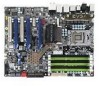
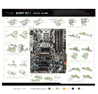
Control Sense 12V Ground CPU Fan Header 8 Pin 12v Power Ground 12V Sense Fan Header 24 Pin ATX Power Please see the manual for more details. 1 4 6 8 SATA Port Ground 12V Sense Fan Header Post LED Connector Pin Front Audio Connector 1 2 2 4 6 8 10 3 4 5 6 7 13 579 8 9 10 Signal PORT1_L AUD_GND PORT1_R PRECENCE J PORT2_R SENSE1_RETURN SENSE_SEND Empty PORT2_L SENSE2_RETURN Connector SPDIF 2 46 1 35 Pin Definition 1 Power 2 No Pin 3 SPDIF 4 SPDIFI 5 GROUND 6 GROUND IDE Channel RXRX+ TXTX+ GND GND GND SATA Ports PC Speaker Serial Connector Pin IEEE 1394a Connector 1 2 2 4 6 8 10 3 4 5 6 7 1 3579 8 9 10 CMOS Power Button Reset Button Signal TPA+ TPAGND GND TPB+ TPB+ 12V + 12V Empty GND Fan Header Ground 12V Sense Ground 12V Sense Connector Pin USB 2.0 Header Connector 1 1 3579 3 5 7 9 2 4 6 8 10 Signal Pin 5V_DUAL 2 D- 4 D+ 6 GND 8 Empty 10 Signal 5V_DUAL DD+ GND No Connect PWRLED PWRSW Blank +- 2 10 1 9 +HD_LED RESET No Connect 2 3 5 2 7 1. PS/2 Keyboard Port 2. USB 2.0 Ports 3. Clear CMOS 4. Coaxial SPDIF Output 5. Optical SPDIF Output 2 9 6. IEEE1394a (Firewire) Port 7. e-SATA Port 8. LAN Ports (10/100/1000) 9. Audio Ports 135 246 One DIMM: If using 1 DIMM (Single Channel), install into: DIMM slot 1. Two or Four DIMMs: If using 2 DIMMs (Dual Channel), install into: DIMM slots 1 and 3. If using 4 DIMMs (Dual Channel), install into: DIMM slots 2, 1, 4, and 3. Three DIMMs: If using 3 DIMMs (Triple Channel), install into: DIMM slots 1, 3, and 5. Six DIMMs: If using more than 4 DIMMs, use: DIMM slots 2, 1, 4, and 3 then proceed to occupy the following DIMM slots in this order: 5 and 6. ATTENTION: EVGA recommends applying 1.65V or less when setting the DIMM Voltage. This will support long term stability. Premium Services dvanced RMA Stepping-Up Your Customer Service Limited Lifetime Warranty upon product registration Support Thank you for purchasing an EVGA product. Please remember to register your product at: www.evga.com/register For the latest drivers and updates for your product please visit: www.evga.com/support/drivers To visit and search our knowledge base and product FAQ please visit: www.evga.com/FAQ To visit the EVGA community message boards please visit: forums.evga.com For more information about these services as well as our terms and conditions please visit www.evga.com EVGA Corp. 2900 Saturn Street, Suite B Brea, CA 92821 Color info : CMYK Please match colors to: PMS © Orange 021 PMS © 485 c PMS © Yellow c PMS © Hexachrome Green PMS © Process Cyan K 100% K 85%
-
 1
1 -
 2
2
 |
 |