EVGA 160-LF-E659-KR User Guide - Page 29
From Right to Left, PCIE Slots 1,2,3. When Jumper is in top position, PCIE
 |
View all EVGA 160-LF-E659-KR manuals
Add to My Manuals
Save this manual to your list of manuals |
Page 29 highlights
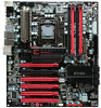
The Red wires should be occupying the pins on the top row. Now, access the Disable/Enable Function at the front of the Control Panel: From Right to Left, PCIE Slots 1,2,3. When Jumper is in top position, PCIE slot is enabled. When in bottom position PCIE slot is disabled. Above shows example of PCIE slot 2 disabled while the rest are enabled. 29
-
 1
1 -
2
-
3
-
4
-
5
-
6
-
7
-
8
-
9
-
10
-
11
-
12
-
13
-
14
-
15
-
16
-
17
-
18
-
19
-
20
-
21
-
22
-
23
-
 24
24 -
 25
25 -
 26
26 -
 27
27 -
 28
28 -
 29
29 -
 30
30 -
 31
31 -
 32
32 -
 33
33 -
 34
34 -
35
-
36
-
37
-
38
-
39
-
40
-
41
-
42
-
43
-
44
-
45
-
46
-
47
-
48
-
49
-
50
-
51
-
52
-
53
-
54
 |
 |

29
The Red wires should be occupying the pins on the top row.
Now, access the Disable/Enable Function at the front of the Control Panel:
From Right to Left, PCIE Slots 1,2,3. When Jumper is in top position, PCIE
slot is enabled. When in bottom position PCIE slot is disabled. Above shows
example of PCIE slot 2 disabled while the rest are enabled.