Electrolux 442B Owners Guide - Page 6
PARTS LIST, HOW TO ASSEMBLE, Attach Floor Nozzle, Attach Handle
 |
UPC - 023169123588
View all Electrolux 442B manuals
Add to My Manuals
Save this manual to your list of manuals |
Page 6 highlights
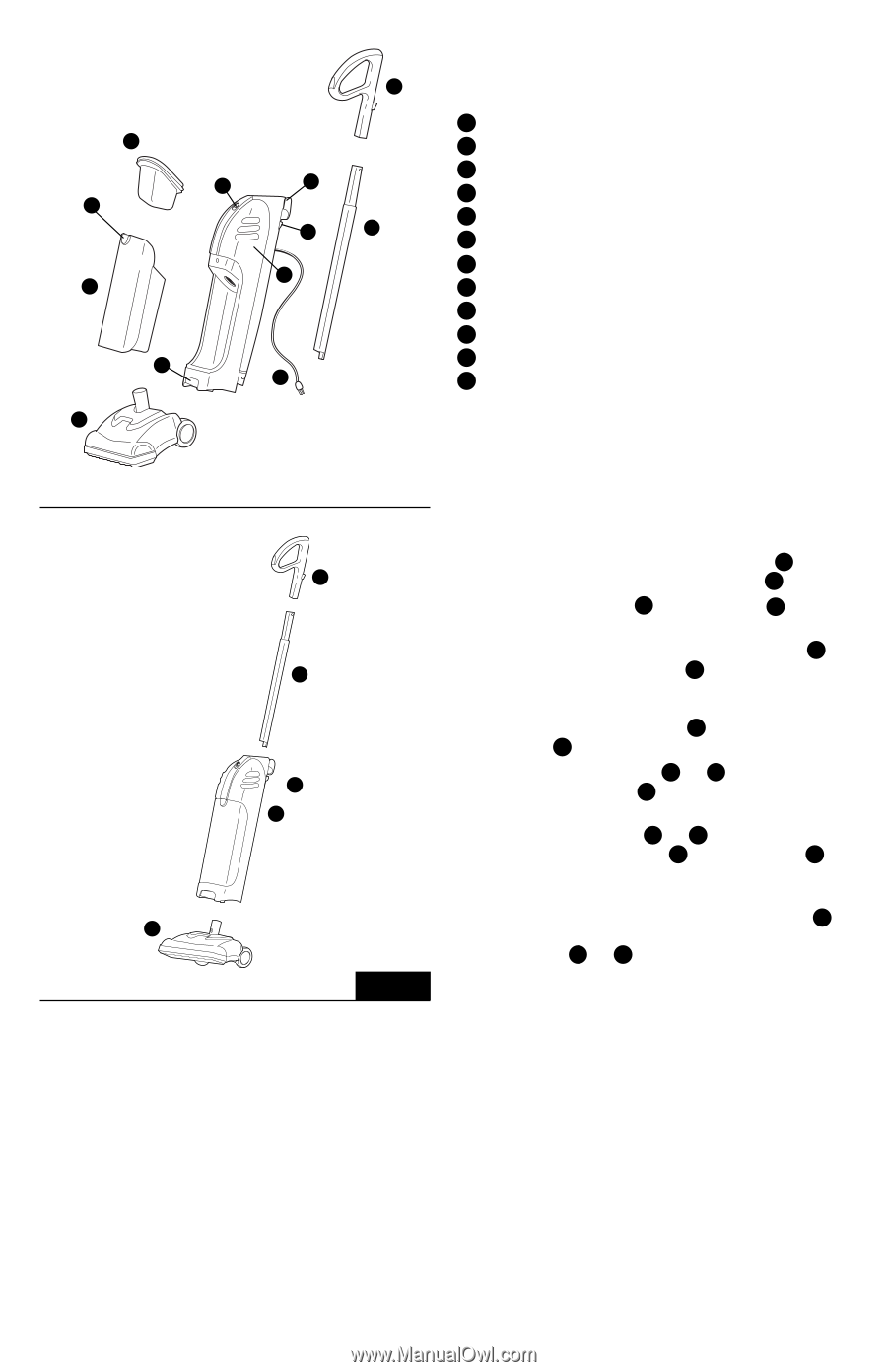
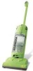
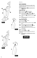
H F G I B B C E L J D A K ENGLISH PARTS LIST A Body B Floor nozzle C Upper handle D Lower handle E Power switch F Dust cup latch G Dust cup H Filter assembly I Stair cleaning hand grip J Handle button K Electrical cord L Quick cord release C D J A FIG. 1 HOW TO ASSEMBLE CAUTION: Assemble the cleaner completely before plugging into an electrical outlet. Make sure switch is in the Off position. Attach Floor Nozzle (Fig. 1) Step 1: Align the lock button on the floor nozzle neck B with the hole in the receiving tube on the main body A . Step 2: Slide the floor nozzle B into the main body A until it clicks into place. Step 3: Push the lock button in and pull on the floor nozzle B to remove it from the main body A . Attach Handle (Fig. 1) Step 1: Align flat side of upper handle C with flat side of lower handle D and press together. Step 2: Line the handle assembly C and D up with the hole in the top of the body A . Flat side of handle and loop should face forward. Step 3: Push handle assembly C and D down into body while pressing the handle button J on back of the body A . Handle will click into place. Step 4: There are two handle positions available: Handle all the way up and handle all the way down. Handle button J needs to be depressed to raise and lower the handle assembly C and D . 6
-
 1
1 -
 2
2 -
 3
3 -
 4
4 -
 5
5 -
 6
6 -
 7
7 -
 8
8 -
 9
9 -
 10
10 -
 11
11 -
 12
12 -
13
-
14
-
15
-
16
-
17
-
18
-
19
 |
 |