Electrolux CEI30EF5GS Service Manual
Electrolux CEI30EF5GS Manual
 |
View all Electrolux CEI30EF5GS manuals
Add to My Manuals
Save this manual to your list of manuals |
Electrolux CEI30EF5GS manual content summary:
- Electrolux CEI30EF5GS | Service Manual - Page 1
FREESTANDING ELECTRIC RANGE PRODUCT SERVICE MANUAL MODELS - EW30EF65G , EI30EF55G , ** ** CEW30EF6G , CEI30EF5G Wave-Touch™ IQ Touch™ EW30EF65 Publication # 5995521555 August 2008 EI30EF565 PN / 316439223 - Electrolux CEI30EF5GS | Service Manual - Page 2
UPPER OVEN Components 35 Electric Range Component Bake Element 35 Lower Oven Component Service 41 (ESEC 30) TROUBLESHOOTING GUIDE Replacing Lower Oven manual is subject to change as product development continues after the date this manual was created. Component Parts 28 Troubleshooting - Electrolux CEI30EF5GS | Service Manual - Page 3
product repair if you have any doubts as to your ability to complete it in a safe and satisfactory manner. 2. Before servicing or moving an appliance: ONLY REPLACEMENT PARTS CATALOGED FOR THIS APPLIANCE. SUBSTITUTIONS MAY DEFEAT COMPLIANCE WITH SAFETY STANDARDS SET FOR HOME APPLIANCES. 5. GROUNDING - Electrolux CEI30EF5GS | Service Manual - Page 4
house wiring attaches to the appliance. Verify that there are 240 parts. When the repair has been completed the product should be thoroughly tested to verify that the service performed corrected the problem servicing Electrolux cooking products gas line pressure on gas ranges. Measurements must be in - Electrolux CEI30EF5GS | Service Manual - Page 5
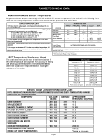
temperature limits outlined in the following chart. Note that the testing temperature is different for electric ranges produced after 08/26/2003. SURFACE TEMPERATURE LIMITS 1. Product must be undamaged, correctly assembled and have the correct oven temperature. 2. All skin temperatures are based - Electrolux CEI30EF5GS | Service Manual - Page 6
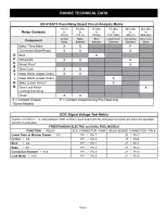
RANGE TECHNICAL DATA ES 610/615 Oven Relay Board Circuit Analysis Matrix Relay Contacts Component P4 (R) to P2 (O) L2 Out Relay P6 (BK) to P10 (Y) Bake - Electrolux CEI30EF5GS | Service Manual - Page 7
TERMS Perfect Pair™ = Lower oven in the drawer below the main oven. Also called a Mini Oven. IQ Touch™ = Control panel display style found on "B" model ranges. Wave-Touch™ = Control panel display style found on "A" model - Electrolux CEI30EF5GS | Service Manual - Page 8
condition. Note: Fault codes are not a foolproof system. Never assume that a part has failed based on a displayed fault code. An example would be if the to be replaced should damage be extensive. 1. Reset power supply to range to see if failure code will clear. 2. Check/reseat ribbon harness - Electrolux CEI30EF5GS | Service Manual - Page 9
RANGE TECHNICAL DATA ELECTRONIC SURFACE ELEMENT CONTROL (ESEC 30) TROUBLESHOOTING GUIDE - Wave Touch Models - For . 3. Replace TST panel. "E 11" In Displays Shorted Keypad 1. Reset power supply to range to see if failure code will clear. 2. Check/reseat ribbon harness and connectors between the - Electrolux CEI30EF5GS | Service Manual - Page 10
RANGE TECHNICAL DATA ELECTRONIC SURFACE ELEMENT CONTROL (ESEC 30) TROUBLESHOOTING GUIDE - IQ Touch Models - For each ESEC error or Signal loss between ESEC 30 UIB and ESEC relay board. Turn off power to range for 30 seconds then reapply power. Does error return within 5 seconds ? YES: Go to - Electrolux CEI30EF5GS | Service Manual - Page 11
Wiring Diagram - Electric Wave Touch Models with Lower Oven Page 11 - Electrolux CEI30EF5GS | Service Manual - Page 12
Schematic Diagram - Electric WaveTouch Models with Lower Oven Page 12 - Electrolux CEI30EF5GS | Service Manual - Page 13
Wiring Diagram - Electric IQ Touch Models with Warming Drawer Page 13 - Electrolux CEI30EF5GS | Service Manual - Page 14
Schematic Diagram - Electric IQ Touch Models with Warming Drawer Page 14 - Electrolux CEI30EF5GS | Service Manual - Page 15
PRODUCT OVERVIEW Electrolux branded freestanding electric ranges are currently available in two distinct model series. also very different from the Wave Touch series as will be seen later in this manual. The oven and warmer drawer functions are controlled by the ES630 Electronic Oven Control. Surface - Electrolux CEI30EF5GS | Service Manual - Page 16
non serviceable part and must be replaced as a complete assembly if found to be defective. The replacement glass panel will come attached to the frame and will include ribbon connectors. (Photo B) Photo A Touch Glass Frame Photo B Troubleshooting . If the problem remains replace the - Electrolux CEI30EF5GS | Service Manual - Page 17
occurred a special Diagnostic Service Mode has been built in to the control panel software. To enter the service mode the range must be in the follow the troubleshooting steps outlined in the tech sheet and this service manual to correct that specific condition. . NOTE: The Diagnostic Service Mode - Electrolux CEI30EF5GS | Service Manual - Page 18
codes that may be displayed to guide the service technician in diagnosing the failure. It no display in either window. Fig 1 The troubleshooting guide below provides a listing of the likely failure 3. Replace TST panel. 1. Reset power supply to range to see if failure code will clear. 2 Check - Electrolux CEI30EF5GS | Service Manual - Page 19
service mode described on page 17 to determine which ESEC error condition is present Fig 1 ELECTRONIC SURFACE ELEMENT CONTROL (ESEC 30) TROUBLESHOOTING GUIDE Solution B - E11 Failure Mode Shorted Keypad 1. Reset power supply to range to see if failure code will clear. 2. Check/reseat ribbon harness - Electrolux CEI30EF5GS | Service Manual - Page 20
oven CONTROL (ES630) The Electrolux branded ranges covered in this manual feature the ES630 Electronic Oven Control display panel has a "sleep mode" that turns off the illuminated control icons on the touch panel whenever the range is idle for 2 minutes (Diag A). During this sleep mode only the - Electrolux CEI30EF5GS | Service Manual - Page 21
Troubleshooting and Testing The Electronic Oven Control system found in the Electrolux freestanding electric ranges servicer must follow the troubleshooting and diagnostic information found in this manual and in the product tech sheet to accurately diagnose any failures and avoid unnecessary parts - Electrolux CEI30EF5GS | Service Manual - Page 22
from the EOC to the Relay board for the particular relay that turns on that component part. When testing the output signal set your volt meter to read DC voltage. The output the EOC circuit board on a gas range. GND (-) CIRCUIT ACCESS POINTS BAKE RELAY SIGNAL VOLTAGE TEST Photo A Page 22 Photo B - Electrolux CEI30EF5GS | Service Manual - Page 23
separate power supply boards that are mounted on the rear of the range chassis just below the EOC as seen in photo A. The two P2. Always test the incoming and outgoing voltage at the power supply boards when troubleshooting EOC or ESEC control failures. Photo A EOC Board Power Supply Board PS 2 - Electrolux CEI30EF5GS | Service Manual - Page 24
properly the VSC board should be examined as a possible source of failure. When testing for convection fan operation it should be noted that on gas ranges there is a six minute delay from the start of the convection cooking cycle until the fan motor will run. Variable Fan Speed To achieve optimum - Electrolux CEI30EF5GS | Service Manual - Page 25
on at full power. If none of the halogen oven lights operate, plug in the range and open the oven door. Test for P2 approximately 120 volts AC at pins 1 bulbs, sockets or wiring connections. If the voltage is incorrect the problem could be caused by a defective door switch, VSC board, or - Electrolux CEI30EF5GS | Service Manual - Page 26
cleaning cycle without removing the racks a message on the EOC will illuminate instructing them to remove the racks. (Photo B). If the racks have been sensor assembly and switch. Part number is 5304468694 and is available through your authorized parts distributor. Page 26 Photo A Mtg. screw - Electrolux CEI30EF5GS | Service Manual - Page 27
RACK SENSING SWITCH To test the rack sense switch contacts remove the rear wire cover on the range and access the wire harness connector P10 on the EOC. (Photo A) Unplug the harness and test for continuity between the blue & grey wires in the - Electrolux CEI30EF5GS | Service Manual - Page 28
Device) similar to the oven temperature sensor found in ranges with electronic oven controls. As the temperature of the Parts The components of the meat probe feature are: Probe assembly (Fig 1 ) and the receptacle assembly which includes the wire harness (Fig 2 ). Fig 1 Fig 2 Troubleshooting - Electrolux CEI30EF5GS | Service Manual - Page 29
servicing the smooth glass cooktop and surface elements is similar to other Electrolux manufactured ranges. The front of the cooktop can be lifted by removing the screws that secure it to the range use a wooden or plastic dowel to support the top while service is performed. (Photo C) With the - Electrolux CEI30EF5GS | Service Manual - Page 30
element. Take note of the terminal identification on the element terminal block for each wire connection. 3. Before the element can be removed from the support channel the locking tab on the mounting clip must be closed by squeezing shut with a pair of pliers. After the repair is complete the tab - Electrolux CEI30EF5GS | Service Manual - Page 31
parts of the Oven Door assembly can be serviced or replaced. The door is not available as a complete assembly. To service the door begin by removing the door Photo A Photo B from the range range. (Photo E) To reinstall the door reverse the previous steps. Use your knee to stabilize and help guide - Electrolux CEI30EF5GS | Service Manual - Page 32
Door Disassembly To service or replace the door components remove the door as previously described and place the door on a protected work surface with the handle side down. Begin - Electrolux CEI30EF5GS | Service Manual - Page 33
two screws found in each trim. (Photo A) REMOVE SCREWS Photo A Remove the air wash glass and mounting brackets by removing the four screws that secure the brackets to the porcelain the color stated in the parts description from the part list. Photo D 7316508700 Hinge Assembly, door, blue Page 33 - Electrolux CEI30EF5GS | Service Manual - Page 34
Door Disassembly Remove the wool shield by taking out the remaining four screws securing the shield to the door liner. (Photo A). Photo A REMOVE SCREWS When reinstalling the wool shield be sure that the bottom edge of the shield is nested under the upturned edge of the porcelain door liner. Photo - Electrolux CEI30EF5GS | Service Manual - Page 35
UPPER OVEN Components Bake Element To remove and replace the bake element remove the oven door and all interior oven racks. Remove the rack sensor assembly by taking out the two screws in the top mounting bracket and lifting the bracket and sensor assembly rod out of the lower bracket. (Photo A) - Electrolux CEI30EF5GS | Service Manual - Page 36
Photo A. Before removing the bake element disconnect the element wires which can be accessed by removing the lower rear shield on the back of the range. (Photo B) Photo A Photo B Broil Element The broil element is eight pass, 240 volts, 4000 watts. It is secured to the oven liner by the six - Electrolux CEI30EF5GS | Service Manual - Page 37
be accessed by removing the lower rear shield on the back of the range. (Photo C) Photo C Rack Sensing Switch Replacement The rack sensing wall. (Photo D) To replace the switch first turn off the power to the range and remove the lower back cover panel. Unplug the harness connector (Photo E) and - Electrolux CEI30EF5GS | Service Manual - Page 38
Halogen Oven Lights Each light assembly houses a replaceable 40 watt bulb behind the clear lens. To remove the lens use a thin bladed screwdriver or putty knife to gently pry the lens out. Take care not to damage the finish of the oven wall. (Photo A) Photo A With the lens removed the bulb can be - Electrolux CEI30EF5GS | Service Manual - Page 39
Glide Oven Racks have no serviceable parts and should be replaced as authorized Electrolux parts supplier under part number 5304468694. This lubricant should also be used on the rack switch sensor rod assembly To lubricate the bearings remove the racks as described in the owners manual - Electrolux CEI30EF5GS | Service Manual - Page 40
rack sensor assembly should be lubricated annually or more often as needed. Use only the approved water based graphite lubricant available through authorized Electrolux parts dealers. NEVER use grease or oil of any kind to lubricate the rack sensor assembly. To lubricate the assembly remove all oven - Electrolux CEI30EF5GS | Service Manual - Page 41
Lower Oven Component Service Replacing Lower Oven Element Remove Drawer Fig. 1 1. Before drawer drawer glides into lower oven cavity. Fig. 2 Fig. 3 Glide Hook Disengaged From the rear of the range remove the six screws that secure the lower rear shield. ( Fig. 5 ) Note that the center screw - Electrolux CEI30EF5GS | Service Manual - Page 42
Replacing Drawer Glide Rails The lower oven drawer glide rails (Fig. 8) clip into Fig. 8 the side wall of the lower oven cavity and are se- cured by one screw in each rail. The mounting screw is accessed through a hole in the glide rail outer track. (Fig. 9) . Fig. 9 Remove Screw Once the - Electrolux CEI30EF5GS | Service Manual - Page 43
connections to the element and cavity light. Remove the drawer per instructions on page 41. Screw Access Using a ¼" nut driver with magnetic forward and removed from the range. (Photo B). With the lower oven chassis removed the insulation and chassis panels can be serviced. NOTE: The lower oven - Electrolux CEI30EF5GS | Service Manual - Page 44
heat until the thermal disk opens. Warmer DRAWER Component Service Removing and Replacing Warmer Drawer To Remove the Warming Drawer and push down on the right glide lever. 5. Pull the drawer away from the range. Photo C To Replace the Warming Drawer: 1. Pull the bearing glides to the front - Electrolux CEI30EF5GS | Service Manual - Page 45
both of the drawer guide rails and side shields have been removed the base pan and element assembly can be pulled forward to remove from the range. (Photo C) Photo B With the element and base pan assembly removed the element and thermo disc are accessible for servicing. (Photo D) To remove the - Electrolux CEI30EF5GS | Service Manual - Page 46
Page 46 - Electrolux CEI30EF5GS | Service Manual - Page 47
NOTES Page 47
-
 1
1 -
 2
2 -
 3
3 -
 4
4 -
 5
5 -
 6
6 -
 7
7 -
8
-
9
-
10
-
11
-
12
-
13
-
14
-
15
-
16
-
17
-
18
-
19
-
20
-
21
-
22
-
23
-
24
-
25
-
26
-
27
-
28
-
29
-
30
-
31
-
32
-
33
-
34
-
35
-
36
-
37
-
38
-
39
-
40
-
41
-
42
-
43
-
44
-
45
-
46
-
47
 |
 |

PN / 316439223
Publication # 5995521555
August 2008
FREESTANDING ELECTRIC RANGE
PRODUCT SERVICE MANUAL
Wave-Touch™
EW30EF65
IQ Touch™
EI30EF565
*
*
MODELS - EW30EF65G
,
EI30EF55G
,
CEW30EF6G
,
CEI30EF5G
*
*