Electrolux CEI30EF5GS Service Manual - Page 24
VARIABLE SPEED CONTROL, Variable Fan Speed
 |
View all Electrolux CEI30EF5GS manuals
Add to My Manuals
Save this manual to your list of manuals |
Page 24 highlights
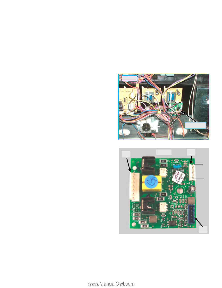
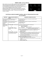
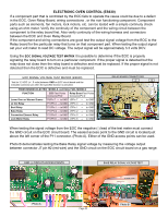
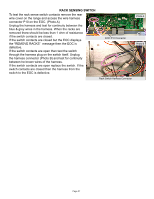
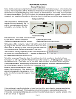
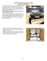
VARIABLE SPEED CONTROL The Variable Speed Control (VSC) board operates the Convection Fan as well as the Oven LUXURY™ lighting. In the event that either of these features do not operate properly the VSC board should be examined as a possible source of failure. When testing for convection fan operation it should be noted that on gas ranges there is a six minute delay from the start of the convection cooking cycle until the fan motor will run. Variable Fan Speed To achieve optimum cooking results during convection cooking the fan motor speed can be varied. The EOC will signal the VSC board to speed up or slow down the fan as needed. This speed change takes place automatically with no action required by the consumer. The VSC Board is located on the rear of the range just below the power supply boards, as seen in photo A. The board varies the voltage to the convection fan motor as directed by the EOC to alter the motor speed. The speed control signal and the power supply to operate the VSC board come from the EOC through a wiring harness connected between P2 on the EOC and P1 on the VSC board. This harness must be intact and properly connected for the VSC board to operate. If the harness is defective or not properly connected the EOC will display a fault code F23. Photo A VSC Board When testing the VSC board the power supply from the EOC to the board can be verified by measuring P2 the voltage between pins 1 & 6 (the two outside pins) on connector P6 of the VSC board. This connector is not wired in field applications and the pins are easily accessed to test voltage while the other harness connectors are in place and power is applied to the range. Test for approximately 5 volts DC (+/- .5 volt) on these two pins. If the EOC appears to operate normally but the voltage to the VSC board is incorrect or if there is no voltage present inspect and test the wire harness and connectors between the EOC and VSC board. If the harness is good then the EOC is defective and should be replaced. Photo B P6 Pin 1 Pin 6 P1 If the convection fan motor fails to run test for voltage to the convection fan motor. If no voltage is present then the failure is either in the VSC board, EOC , or the wiring in between. If there is proper voltage to the fan motor but it does not run then either the motor windings are open or the motor is stuck. Test the continuity of the motor windings with an ohm meter. There should be approximately 15 ohms of resistance in the convection fan motor windings. If the windings test good inspect the fan blade and motor shaft to see if the motor will turn. Adjust the fan blade to eliminate binding or replace the motor assembly if the motor shaft is seized. Page 24
-
 1
1 -
2
-
3
-
4
-
5
-
6
-
7
-
8
-
9
-
10
-
11
-
12
-
13
-
14
-
15
-
16
-
17
-
18
-
 19
19 -
 20
20 -
 21
21 -
 22
22 -
 23
23 -
 24
24 -
 25
25 -
 26
26 -
 27
27 -
 28
28 -
 29
29 -
30
-
31
-
32
-
33
-
34
-
35
-
36
-
37
-
38
-
39
-
40
-
41
-
42
-
43
-
44
-
45
-
46
-
47
 |
 |