Electrolux E30MC75PPS Installation Instructions English
Electrolux E30MC75PPS Manual
 |
View all Electrolux E30MC75PPS manuals
Add to My Manuals
Save this manual to your list of manuals |
Electrolux E30MC75PPS manual content summary:
- Electrolux E30MC75PPS | Installation Instructions English - Page 1
INSTRUCTIONS INSTALLATION AND SERVICE MUST BE PERFORMED BY A QUALIFIED INSTALLER. IMPORTANT: SAVE FOR LOCAL ELECTRICAL INSPECTOR'S USE. READ AND SAVE THESE INSTRUCTIONS Electrical Junction Box Figure 1 NOTES: 1. Base must be capable of supporting 275 pounds (125 kg) for 27" models and 350 pounds ( - Electrolux E30MC75PPS | Installation Instructions English - Page 2
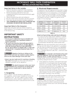
Guide for future reference. Do not discard oven removal tools found in the literature bag. IMPORTANT SAFETY INSTRUCTIONS • Be sure your combination oven is installed and grounded properly by a qualified installer or service oven. The oven support surface may be Electrical Code, Part 1, and local - Electrolux E30MC75PPS | Installation Instructions English - Page 3
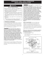
MICROWAVE/ WALL OVEN COMBINATION INSTALLATION INSTRUCTIONS Electrical Shock Hazard • Electrical ground is required on this /NFPA No. 70-latest edition, or with CSA Standard C22.1, Canadian Electrical Code, Part 1, and local codes and ordinances. Risk of electrical shock (Failure to heed this warning - Electrolux E30MC75PPS | Installation Instructions English - Page 4
when the door is opened. When ordering parts for or making inquires about your oven, move and install wall oven. • Failure to follow this instruction can result in injury or damage to the unit. 1 door up and toward you to disengage the hinge supports. Keep pulling the bottom of the door toward - Electrolux E30MC75PPS | Installation Instructions English - Page 5
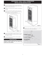
3 Remove all packaging inside the ovens and remove the lower oven racks and their supports (see owner's guide for further instructions). 4 Find the 2 mounting screws included in the literature package. 5 Insert the unit into the cabinet opening. Slide unit inward leaving 1½" (3.8 cm) clearance - Electrolux E30MC75PPS | Installation Instructions English - Page 6
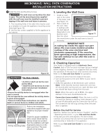
level if necessary. IMPORTANT NOTE A cooling fan inside the upper rear part above the oven (some models) provides cooling of the oven electrical Before You Call for Service Read the "Before You Call for Service Checklist" and the "Operating Instructions" in your Use and Care Guide. It may save you - Electrolux E30MC75PPS | Installation Instructions English - Page 7
MICROWAVE/ WALL OVEN COMBINATION INSTALLATION INSTRUCTIONS LA INSTALACIÓN Y EL SERVICIO DEBEN SER EFECTUADOS POR UN INSTALADOR será necesario. No quite los separadores de los muros laterales o/y de la parte posterior del horno empotrado. Estos espaciadores centran el horno en el espacio provisto. - Electrolux E30MC75PPS | Installation Instructions English - Page 8
COMBINATION INSTALLATION INSTRUCTIONS Notas importantes para el instalador 1. Lea todas las instrucciones contenidas en este manual antes ón en los Estados Unidos, o el Código Eléctrico Canadiense CSA Standard C22.1, Part 1, en Canadá. Pisar, apoyarse, o sentarse sobre la puerta de este horno de - Electrolux E30MC75PPS | Installation Instructions English - Page 9
MICROWAVE/ WALL OVEN COMBINATION INSTALLATION INSTRUCTIONS Riesgo de choque eléctrico • Una puesta a tierra se 70-última edición en los Estados Unidos, o el Código Eléctrico Canadiense CSA Standard C22.1, Part 1, en Canadá. Riesgo de choque eléctrico (El no prestar atención a esta advertencia puede - Electrolux E30MC75PPS | Installation Instructions English - Page 10
MICROWAVE/ WALL OVEN COMBINATION INSTALLATION INSTRUCTIONS Si el horno se usa en una instalación de circuito de ramal nuevo (1996 NEC), en una casa rodante, en un vehículo para recreación o - Electrolux E30MC75PPS | Installation Instructions English - Page 11
MICROWAVE/ WALL OVEN COMBINATION INSTALLATION INSTRUCTIONS 3 Quite todo el material de empaque del interior de y hacia la caja de paso mientras se desliza el accesorio hacia adentro. 7 Colocar la parte superior de la guarnición inferior sobre las lengüetas laterales del horno, debajo de la puerta - Electrolux E30MC75PPS | Installation Instructions English - Page 12
INSTALLATION INSTRUCTIONS 9 Instalaci si sea necesario. NOTA IMPORTANTE Un ventilador ubicado dentro de la parte trasera superior arriba del horno (en algunos modelos) permite la servicio Lea la sección Lista de Antes de llamar en su Manual del Usuario. Esto le podrá ahorrar tiempo y gastos. Esta - Electrolux E30MC75PPS | Installation Instructions English - Page 13
LISEZ ET CONSERVEZ CES INSTRUCTIONS POUR RÉFÉRENCES ULTÉRIEURES si nécessaire (note 4). Figure 1 1.La base doit pouvoir supporter 275 lbs (125 kg) pour les **4. Si la hauteur de plus haute de qu'elle est correcte. votre centre de service. DIMENSIONS DE L'APPAREIL MODÈLE A B C D Four - Electrolux E30MC75PPS | Installation Instructions English - Page 14
. 4. Assurez-vous de laisser ces instructions au consommateur. 5. La porte du terre conformément par un installateur ou un technicien de service qualifié. • Ce four encastré doit être mis nécessaire pour recevoir l'appareil. La surface qui supporte l'appareil doit être en contre-plaqué solide ou - Electrolux E30MC75PPS | Installation Instructions English - Page 15
. • N'utilisez pas un tuyau d'alimentation de gaz pour la mise à la terre de l'appareil. Si vous ne respectez pas toutes les instructions précédentes, un feu, des blessures corporelles ou un choc électrique peuvent en résulter. 3. Connexions électriques Le consommateur est responsable et doit - Electrolux E30MC75PPS | Installation Instructions English - Page 16
ou des dommages à l'appareil peuvent survenir si vous ne suivez pas cette instruction. 1 Déballez le four encastré et récupérez la moulure inférieure , soulevez légèrement la porte et tirez-la vers vous pour dégager les supports de charnières. Continuez à tirer la porte vers vous en faisant pivoter - Electrolux E30MC75PPS | Installation Instructions English - Page 17
INSTRUCTIONS D'INSTALLATION POUR LE MODÈLE COMBINÉ FOUR À ENCASTRER/FOUR À MICRO-ONDES 3 Retirez tous l'emballage et les accessoires des fours et retirez aussi les grilles et les supports de grilles du four inférieur (voir manuel d'utilisation pour plus de détails). 4 Localisez les vis de fixation - Electrolux E30MC75PPS | Installation Instructions English - Page 18
ère tourne. Le ventilateur convection arrête lorsque l'on ouvre la porte du four. Avant d'appeler le service d'entretien Réviser la liste de vérifications préventives et les instructions d'opération dans votre Manuel d'utilisation et d'entretien. Vous sauverez probablement du temps et de l'argent. La - Electrolux E30MC75PPS | Installation Instructions English - Page 19
NOTES/ NOTAS 19 - Electrolux E30MC75PPS | Installation Instructions English - Page 20
NOTES/ NOTAS 20
-
 1
1 -
 2
2 -
 3
3 -
 4
4 -
 5
5 -
 6
6 -
 7
7 -
8
-
9
-
10
-
11
-
12
-
13
-
14
-
15
-
16
-
17
-
18
-
19
-
20
 |
 |
MICROWAVE/ WALL OVEN COMBINATION
INSTALLATION INSTRUCTIONS
INSTALLATION AND SERVICE MUST BE PERFORMED BY A QUALIFIED INSTALLER.
IMPORTANT: SAVE FOR LOCAL ELECTRICAL INSPECTOR'S USE.
READ AND SAVE THESE INSTRUCTIONS FOR FUTURE REFERENCE.
FOR YOUR SAFETY: Do not store or use gasoline or other
flammable vapors and liquids in the vicinity of this or any other appliance.
All dimensions are in inches (cm).
Printed in United States
U.S.A. & Canada
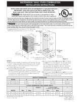
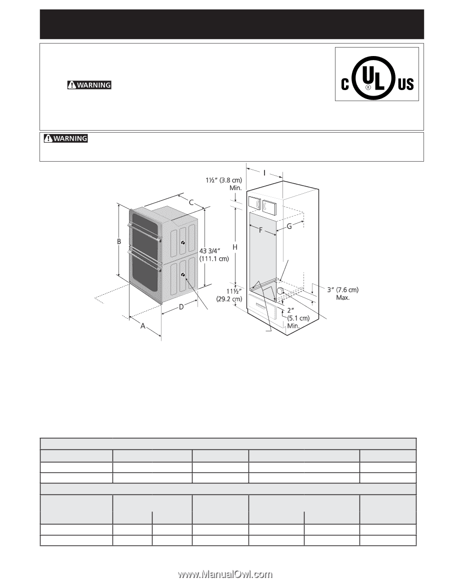
Figure 1
Do not remove spacers (if equipped) on the side walls and/or on the back of the built-in
oven. These spacers center the oven in the space provided.
The oven must be centered to prevent excess
heat buildup that may result in heat damage or fire.
NOTES:
1.
Base must be capable of supporting 275 pounds (125 kg)
for 27" models and 350 pounds (159 kg) for 30" models.
2.
Allow at least 21" (53.3 cm) clearance in front of oven
for door depth when it is open.
3.
Dimension
G
(cutout depth) is critical to the proper
installation of the built-in oven. If the oven decorative
trim does not butt against the cabinet, or if noise is heard
on convection models, verify dimension
G
to assure it is
according to the required dimension.
**4.
For a cutout height
(H)
between
44"
(111.8cm)
and
44
5
/
8
"
(113.3 cm) add a 2" (5 cm) wide wood
shim of appropriate height to each side of the
opening under the appliance side rails. Lifting the
unit will allow you to hide the cutout openings
showing above the unit. The bottom trim of the unit
will hide the shims at the bottom.
**5.
For a cutout height
(H)
between
44
5
/
8
"
(113.3 cm)
and
46
3
/
8
"
(117.8 cm) you can order a larger bottom
trim through your Service Center.
Door Open
(see note 2)
Hole for
Cable
Electrical
Junction Box
2" (5 cm) Wide Wood Spacer
if Needed (see note 4)
Spacer
*
Suggested distance from floor is 11½" (29.2 cm).
Minimum required distance is 4 ½" (11.4 cm).
*
PRODUCT DIMENSIONS
MODEL
A
B
C
D
27" (68.6 cm) Wall Oven
27 (68.6)
45
1
/
4
(114.9)
25
1
/
8
(63.8)
24½ (62.2)
30" (76.2 cm) Wall Oven
30 (76.2)
45
1
/
4
(114.9)
28¼ (71.8)
24½ (62.2)
CUTOUT DIMENSIONS AND CABINET WIDTH
F
G (Min.)
H. Standard Height
(**Others, see notes 4 & 5)
I
MODEL
Min.
Max.
Min.
Max
.
27" (68.6 cm) Wall Oven
25
3
/
8
(64.5)
25
7
/
8
(65.7)
23½ (59.7)
43
7
/
8
(111.3)
44 (111.8)
27
1
/
8
(68.9) Min
30" (76.2 cm) Wall Oven
28½ (72.4)
29 (73.7)
23½ (59.7)
43
7
/
8
(111.3)
44 (111.8)
30
1
/
8
(76.5) Min
Your new wall oven has been designed to fit a limited variety of cutout sizes to make the job of installing easier.
The first step of your installation should be to measure your current cutout dimensions and compare them to the
cutout dimensions chart below for your model. You may find little or no cabinet work being necessary.
P/N 807611002 (1308) Rev. A
English – pages 1-6
Español -paginas 6-12
Français -pages 13-18