Electrolux EI24ID30QS Wiring Diagram (English) - Page 1
Electrolux EI24ID30QS Manual
 |
View all Electrolux EI24ID30QS manuals
Add to My Manuals
Save this manual to your list of manuals |
Page 1 highlights
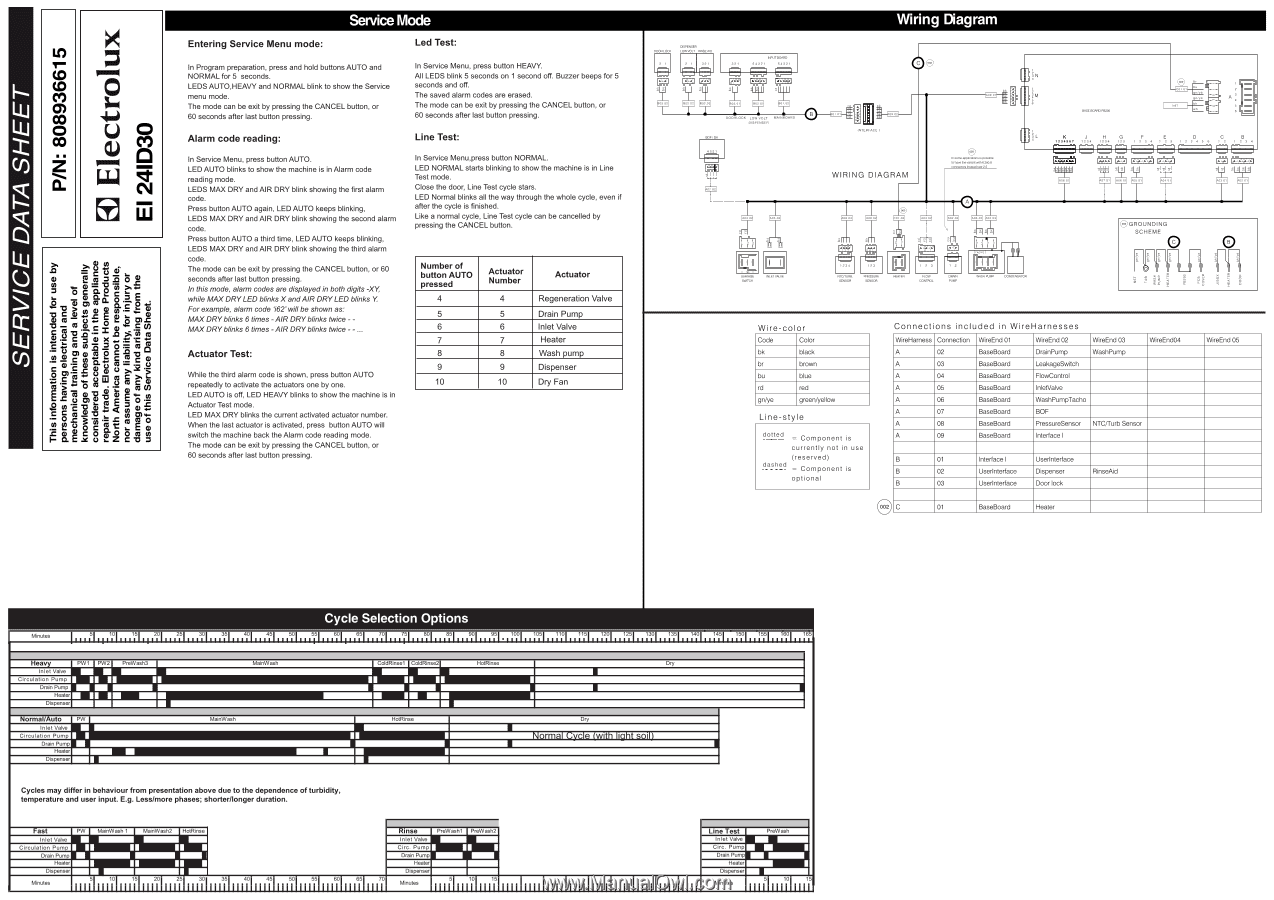
SERVICE DATA SHEET P/N: 808936615 O Ucu 0 w Entering Service Menu mode: Service Mode Led Test: In Program preparation, press and hold buttons AUTO and NORMAL for 5 seconds. LEDS AUTO,HEAVY and NORMAL blink to show the Service menu mode. The mode can be exit by pressing the CANCEL button, or 60 seconds after last button pressing. Alarm code reading: In Service Menu, press button AUTO. LED AUTO blinks to show the machine is in Alarm code reading mode. LEDS MAX DRY and AIR DRY blink showing the first alarm code. Press button AUTO again, LED AUTO keeps blinking, LEDS MAX DRY and AIR DRY blink showing the second alarm code. Press button AUTO a third time, LED AUTO keeps blinking, LEDS MAX DRY and AIR DRY blink showing the third alarm code. The mode can be exit by pressing the CANCEL button, or 60 seconds after last button pressing. In this mode, alarm codes are displayed in both digits -XY, while MAXDRYLED blinks X andAIR DRYLED blinks Y For example, alarm code '162' will be shown as: MAXDRYblinks 6 times -AIR DRYblinks twice - MAXDRYblinks 6 times -AIR DRYblinks twice - - Actuator Test: While the third alarm code is shown, press button AUTO repeatedly to activate the actuators one by one. LED AUTO is off, LED HEAVY blinks to show the machine is in Actuator Test mode. LED MAX DRY blinks the current activated actuator number. When the last actuator is activated, press button AUTO will switch the machine back the Alarm code reading mode. The mode can be exit by pressing the CANCEL button, or 60 seconds after last button pressing. In Service Menu, press button HEAVY. All LEDS blink 5 seconds on 1 second off. Buzzer beeps for 5 seconds and off. The saved alarm codes are erased. The mode can be exit by pressing the CANCEL button, or 60 seconds after last button pressing. Line Test: In Service Menu,press button NORMAL. LED NORMAL starts blinking to show the machine is in Line Test mode. Close the door, Line Test cycle stars. LED Normal blinks all the way through the whole cycle, even if after the cycle is finished. Like a normal cycle, Line Test cycle can be cancelled by pressing the CANCEL button. Number of button AUTO pressed 4 5 6 7 8 9 10 Actuator Number Actuator 4 Regeneration Valve 5 Drain Pump 6 Inlet Valve 7 Heater 8 Wash pump 9 Dispenser 10 Dry Fan DOOR LOC DISPENSER LOWVOLT RI AD 921 .921 INPUT MAID 84921 Wiring Diagram BO 0 BO 0 BO 0 B DOOR LOCK LOW VOLT AINBOARD DISPENSER BOP/ RH BO 0 INTERFACE I WIRING DIAGRAM O = In some applications laps:Ale 40havethe......116.99.8 connector.... reetZE O N M SASE BOARD PB200 0 br en/ye A L J H G C B K 12.567 12. 1234 123 F 0 1 2 3 4 1 2 3 1 2 3 4 5 6 12 1294 • GROUNDING SCHEME I Roar, SWRCH INLETVALVE NTGTURR. SINSOR PRESSURE SENSOR FEATER FLOW CCNTROL WASH PUIR CONDENSATCR Wire -color Code Color bk black br brown bu blue rd red gn/ye green/yellow Line-sty e dotted = Component is currently not in use (reserved) dashed = Component is optional Connections included in WireHarnesses WireHarness Connection WireEnd 01 A 02 BaseBoard WireEnd 02 DrainPump WireEnd 03 WashPump WireEnd04 A 03 BaseBoard LeakageSwitch A 04 BaseBoard FlowControl A 05 BaseBoard InletValve A 06 BaseBoard WashPumpTacho A 07 BaseBoard B0F A 08 BaseBoard PressureSensor NTC/Turb Sensor A 09 BaseBoard Interface I B 01 Interface I Userinterface B 02 Userinterface Dispenser RinseAid B 03 Userinterface Door lock C 01 BaseBoard Heater WireEnd 05 Minutes I Irr rr .1.01 Cycle Selection Options 501 . 2.01 251 301 351 .4.01 451 rrrr t,5 601 651 701 iyl 801 65 I I rr Irr 901 951 1001 1051 1101 1151 1201 1. 2j .14i51 1301 1351 1401 1. 5.01 1551 1601 165 I Heavy Inlet Valve Circulation Pump Drain Pump Heater Dispenser PW1 . PW2 . Normal/Auto PW Inlet Valve Circulation Pump Drain Pump Heater Dispenser PreWash3 . MainWash MainWash ColdRinsel CddRinse2 HotRinse Dry M HotRinse Dry Normal Cycle (with light soil) Cycles may differ in behaviour from presentation above due to the dependence of turbidity, temperature and user input. E.g. Less/more phases; shorter/longer duration. Fast PW MainWash 1 MainWash2 HotRinse - 'rise M=Ilil=3 Inlet Valve Inlet Valve Circulation Pum. Circ. Pump I II I Drain Pump Drain Pump Heater Heater Dispenser Dispenser Minutes 51 101 151 201 25 301 351 401 451 501 551 601 651 70 111111111111111111111111 11111111111111111111111111111111111111111111 Minutes 1 11 15 1.I 1 1I.1 1.I 1 1I.1 1.I 1 1I.1 1.I 1111I.1 me est Inlet Valve Circ. Pump • Drain Pump Heater Dispenser PreWash I Minutes 1111111111111111
-
 1
1 -
 2
2
 |
 |