Electrolux FMV156DB Installation Instructions - Page 3
Tools Recommended For, Installation, Installation Hardware, Hood Exhaust Duct
 |
View all Electrolux FMV156DB manuals
Add to My Manuals
Save this manual to your list of manuals |
Page 3 highlights
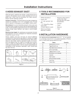
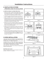
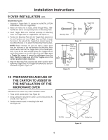
Installation Instructions 4 HOOD EXHAUST DUCT When the hood is vented to the outside, a hood exhaust duct is required. All ductwork must be metal; absolutely do not use plastic duct. Check that all connections are made securely. Please read the following carefully: Exhaust connection: The hood exhaust has been designed to connect to a standard 3-1/4" X 10" rectangular duct. If round duct is required, a rectangular-to-round adapter must be used. Rear exhaust: If a rear or horizontal exhaust is to be used, care should be taken to align the exhaust with the space between the studs, or wall should be prepared at the time it is constructed by leaving enough space between wall studs to accommodate exhaust. Maximum duct length: For satisfactory air movement, the total duct length of 3-1/4" X 10" rectangular or 6" diameter round duct should not exceed 140 feet. Elbows, adapters, wall caps, roof caps, etc. present additional resistance to air flow and are equivalent to a section of straight duct which is longer than their actual physical size. When calculating the total length, add the equivalent lengths of all transitions and adapters plus the length of all straight duct sections. Figure 3 shows the approximate feet of equivalent length of some typical ductwork parts. Use the values in parentheses for calculating air flow resistance equivalent, which should total less than 140 feet. Figure 3 5 TOOLS RECOMMENDED FOR INSTALLATION • Phillips Screwdriver • Electric Drill • 1/2", 5/8" and 3/32" Drill Bits • 1-1/2" Wood Bit or Metal Hole Cutter (if metal cabinet is used) • Saw to cut exhaust opening (if needed) • Protective Drop Cloth for product and range you may also use carton for protection • Scissors • Pencil • Measure • Tape 6 INSTALLATION HARDWARE The INSTALLATION HARDWARE items (1 - 7) are packed in a small bag. Items 8- " are packed separately. All items are in a small carton packed below the oven. Item 1 2 3 4 5 6 7 8 9 ! " Name Wood Screw 5 X 30 mm Toggle Bolt with nuts Top Cabinet Screw 5 X 60 mm Power Cord Hanger Tapping Screw 4 x 12 mm Flat Washer 30 mm diameter Grommet Rear Cushion Exhaust Damper Assembly Scale Plate Grease Filter Quantity 6 4 2 1 3 2 1 1 1 2 2 Figure 4 Parts shown not to common scale. 3
-
 1
1 -
 2
2 -
 3
3 -
 4
4 -
 5
5 -
 6
6 -
 7
7 -
 8
8
 |
 |
