Epson 5700i Service Manual
Epson 5700i - EPL B/W Laser Printer Manual
 |
UPC - 010343818620
View all Epson 5700i manuals
Add to My Manuals
Save this manual to your list of manuals |
Epson 5700i manual content summary:
- Epson 5700i | Service Manual - Page 1
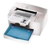
Monochrome Page Printer EPSON EPL-5700L/5700i ® SEPG99007 - Epson 5700i | Service Manual - Page 2
in any form or by any means, electronic, mechanical, photocopying, recording, or otherwise, without the prior written permission of SEIKO EPSON CORPORATION. The contents of this manual are subject to change without notice. All efforts have been made to ensure the accuracy of the contents of this - Epson 5700i | Service Manual - Page 3
3. WHEN PERFORMING TESTING AS DICTATED WITHIN THIS MANUAL, DO NOT CONNECT THE UNIT TO A POWER SOURCE UNTIL INSTRUCTED TO DO SO. WHEN THE POWER SUPPLY NOT CONNECT IT TO THE POWER SOURCE. 3. ALWAYS VERIFY THAT THE EPSON PRODUCT HAS BEEN DISCONNECTED FROM THE POWER SOURCE BEFORE REMOVING OR REPLACING - Epson 5700i | Service Manual - Page 4
PREFACE This manual describes basic functions, theory of electrical and mechanical operations, maintenance and repair procedures of EPL-5700L/5700i. The instructions and procedures included herein are intended for the experienced repair technicians, and attention should be given to the precautions - Epson 5700i | Service Manual - Page 5
Revision A Revision Status Issued Date September 2, 1999 Description First Release - Epson 5700i | Service Manual - Page 6
EPL-5700L/5700i Table of Contents Revision A PRODUCT DESCRIPTION FEATURES 8 BASIC SPECIFICATIONS 10 PAPER SPECIFICATIONS 15 PANEL OPERATION of Controller 22 TROUBLESHOOTING OVERVIEW 26 Overview 26 Electric Check Point 26 HANDLING SERVICE CALL ERRORS 27 Service Call Error Conditions - Epson 5700i | Service Manual - Page 7
PRODUCT DESCRIPTION - Epson 5700i | Service Manual - Page 8
speed RESTRICTIONS / DIFFERENCES WITH EPL-5700 1. A network I/F, including external attachment cannot be used. 2. Fonts are not installed. 3. The emulation is not installed. 4. Only the Windows 95/98, Windows NT 4.0 and Macintosh operating systems (8.1 or later) are supported. 5. The ROP and fill - Epson 5700i | Service Manual - Page 9
EPL-5700L/5700i 12. The recommended host environments are: W indows: Pentium 233 MHz and 64 MB RAM or more M acintosh: G3 233 MHz and 64 MB RAM or more 13. For Windows NT 4.0, EPSON Printer Port Monitor must be installed to use ECP. 14. Even if the option RAM is expanded by 16 MB or more, only a - Epson 5700i | Service Manual - Page 10
SPECIFICATIONS The EPL-5700L/5700i is a compact host-based A4 monochrome page printer that is driven by laser and digital photographic technology. The following shows basic specifications. PROCESS Print M ethod: Light Source: Photoelectric Unit: Charge: D e v e lo p e r: Toner Transfer M ethod - Epson 5700i | Service Manual - Page 11
EPL-5700L/5700i Revision A PAPER HANDLING Paper Supply: Optional Cassette: 150-sheet Cassette-like M ultipurpose Tray M anual Feed Slot 500-sheet A4 Lower Cassette Unit Paper Supply Multipurpose Tray Manual Feed Slot Lower Cassette Table 1-1. Paper Handling Capacity Paper Size 76.2 x 127 to - Epson 5700i | Service Manual - Page 12
EPL-5700L/5700i SOFTWARE SPECIFICATIONS This printer is host-based, nam ely, the host com puter (printer driver) generates print im ages. Refer to the software guide for details. ENVIRONMENTAL CONDITIONS Tem perature (including expendable parts): O p e ra tio n : 10 to 35 °C Storage under norm - Epson 5700i | Service Manual - Page 13
EPL-5700L/5700i DIMENSIONS Dim ensions: W eight: M ain Unit: 397m m (W ) x 493m m (L) x 251m m (H) Approx. 7.5kg RELIABILITY AND DURABILITY Product Life: Approx. 180,000 printed pages or five years, whichever com es first MPBF: 25,000 sheets or more MTBF: 3,000 hours (10 m onths) or m ore - Epson 5700i | Service Manual - Page 14
EPL-5700L/5700i Revision A APPLICABLE CERTIFICATION STANDARDS AND REGURATIONS The specifications 3548 (Australia) Power Consum ption: O thers: In com pliance with international Energy Star standards. Toner: Does not affect hum an body (in accordance with OSHA, TSCA, EINECS and CSCL). OPC: - Epson 5700i | Service Manual - Page 15
-5700L/5700i Revision A 1.3 PAPER SPECIFICATIONS The types of paper which can be used with EPL-5700L/5700i are described b e lo w . PAPER TYPES Normal Paper: Special Paper: PPC, recycled paper 60 to 90g/m 2 (16 to 24lbs) Labels, Japanese official postcards, OHP film s, color paper, thick paper - Epson 5700i | Service Manual - Page 16
EPL-5700L/5700i PAPER SIZE Paper Type Normal Paper Special Paper Table 1-6. Paper Size Paper Size mm (inch) Paper Tray A4 A5 JIS-B5 Letter Half Letter Legal EXE Government Legal Government Letter F4 Postcard Monarch C10 DL C5 C6 InternationalB5 210 x 297 148 x - Epson 5700i | Service Manual - Page 17
(including paper out) OFF ON Service call error Since the EPL-5700L/5700i is a host-based printer, printer 1 settings cannot be made on the control panel. Status sheet can be printed from the printer driver - Epson 5700i | Service Manual - Page 18
EPL-5700L/5700i 1.5 RAM EXPANSION If m em ory shortage occurs, the printer outputs a m isprint and an error m essage appears on the host screen. In such a case, it is necessary to install expansion m em ory RAM (RAM SIM M ). The recom m ended RAM capacity for conditions of use are as shown below. - Epson 5700i | Service Manual - Page 19
EPL-5700L/5700i 1.6 OPTIONS AND CONSUMABLE PRODUCTS Optional lower cassette unit and printer cables for EPL-5700L/5700i are the sam e as options for EPL-5700. Revision A PRODUCT DESCRIPTION OPTIONS AND CONSUMABLE PRODUCTS 19 - Epson 5700i | Service Manual - Page 20
OPERATING PRINCIPLES - Epson 5700i | Service Manual - Page 21
EPL-5700L/5700i 2.1 OPERATING PRINCIPLES OF MECHANISM The EPL-5700L/5700i adopts the sam e m echanism as used in the previous m odel. Refer to the EPL-5700 Service M anual for the detailed operating principles of each m echanism . Revision A OPERATING PRINCIPLES OPERATING PRINCIPLES OF MECHANISM - Epson 5700i | Service Manual - Page 22
EPL-5700L/5700i Revision A 2.2 ELECTRIC CIRCUIT Since the Electric Circuit of this printer is basically the sam e as that of functions as a controller of the printer, consists of the M ain Controller and the Engine Controller. Main Controller TUSB USB I/F DRAM CPU SLC Parallel I/F - Epson 5700i | Service Manual - Page 23
IC (IC6) Reg. PQ3DZ13 ELECTRIC CIRCUIT CN207 Figure 2-2. Block Diagram of the C292 Main Board CN1 D15-0 16 16 RAMSIMM 72pin CN5 USB 4pin TSUB 64pin (5/3.3V) E05B69NA (IC21) 48MHz 3.3V Parallel 36pin LV161284 48pin (IC7) Engine Controller CN3 SLC 208pin (5/3.3V) E05B68NA (IC5) 3.3V - Epson 5700i | Service Manual - Page 24
EPL-5700L/5700i Table 2-1. C292 Main Board - Main Controller Name Location Functions CPU 100MHz ASIC (TUSB) E05B69NA IC21 Controls USB I/F. Package: 64 pin, QFP Power supply voltage: 5V/3.3V Operation frequency: max 48MHz TTL SN74LV162184DGGR 1284 driver. Receives / sends parallel I/F IC7 - Epson 5700i | Service Manual - Page 25
TROUBLESHOOTING - Epson 5700i | Service Manual - Page 26
the instructions of the pop-up window. Also refer to the section "Troubleshooting" of the EPL-5700L/5700i User's Guide, which gives instructions for solving general problem s. 3.1.2 Electric Check Point Refer to 3.2 of the EPL-5700 Service M anual. Revision A TROUBLESHOOTING OVERVIEW 26 - Epson 5700i | Service Manual - Page 27
Main Board. Software Error • Reboot the host PC. • Reinstall the driver. • Replace the Main Board. E0003 E2000 Abnormal Fusing Refer to 3.4.2.3 of the EPL-5700 Service Manual. E0006 Abnormal Polygon Motor Refer to 3.4.2.2 of the EPL-5700 Service Manual. E0009 E0014 Abnormal Laser Refer to - Epson 5700i | Service Manual - Page 28
EPL-5700L/5700i RESETTING EEPROM 1. Open the printer's "Properties" (or "Document Defaults" for Windows NT4.0), and select "Optional Settings". 2. Click the left button of the be reset. The above function should not be made open to users. Revision A TROUBLESHOOTING HANDLING SERVICE CALL ERRORS 28 - Epson 5700i | Service Manual - Page 29
DISASSEMBLY AND ASSEMBLY - Epson 5700i | Service Manual - Page 30
4.1 OVERVIEW The following parts and units of the EPL-5700L/5700i are different from those of EPL-5700. Control Panel Top cover securing m ethod Main Board USB I/F The other m echanism and exterior parts are exactly the sam e as used in EPL-5700. Therefore, this chapter contains the disassem bly and - Epson 5700i | Service Manual - Page 31
m odel, the EPL-5700L/5700i has only two LED lam ps and no other functions on the control panel. However, exterior of the panel is exactly the sam e as the previous m odel, and so is the way the panel is fixed on the printer. Refer to the EPL-5700 Service M anual (pp. 4 - 10) for the Control - Epson 5700i | Service Manual - Page 32
EPL-5700L/5700i Revision A 5. Remove a screw (CS M3x8) and a plate located on the upper part of the shield cover of the Main Control Board (see Figure 4-3 below). 6. Push - Epson 5700i | Service Manual - Page 33
which are connected to the connector on the Main Control Board. 6. Remove 10 screws (CS M3x8) securing the Main Control Board on the printer (See section 4.2.9 of the EPL-5700 Service Manual). 7. Remove a fixing screw for USB interface (CS M3x6) and two fixing screws for parallel interface (CP M3x6 - Epson 5700i | Service Manual - Page 34
ADJUSTMENTS - Epson 5700i | Service Manual - Page 35
EPL-5700L/5700i Refer to the EPL-5700 Service M anual, Chapter 5 for adjustm ent procedures. Revision A ADJUSTMENTS 35 - Epson 5700i | Service Manual - Page 36
MAINTENANCE - Epson 5700i | Service Manual - Page 37
EPL-5700L/5700i Refer to the EPL-5700 Service M anual, Chapter 6 for m aintenance procedures. Revision A MAINTENANCE 37 - Epson 5700i | Service Manual - Page 38
APPENDIX - Epson 5700i | Service Manual - Page 39
Reference CN1 EPL-5700 Service For Expanded RAMSIMM, 72 pin Manual, Table 7-5 and 7-7 CN2 Parallel Interface, 36 pin EPL-5700 Service Manual, Table 7-8 CN3 Video (not used) - CN4 Control Panel (LED Control) - CN5 USB Interface Table 7-2 CN202 Fusing Thermister - CN203 Paper Feed - Epson 5700i | Service Manual - Page 40
EPL-5700L/5700i Table 7-2. Connector CN5 Pin No. Signal Name Direction Function 1 POWER - Cable Power Supply 2 D- Bi-directional Data Signal 3 D+ Bi-directional Data Signal 4 GND - Ground Revision A APPENDIX CONNECTOR PIN ASSIGNMENTS 40 - Epson 5700i | Service Manual - Page 41
EPL-5700L/5700i 7.2 CIRCUIT BOARD COMPONENT LAYOUT Revision A Figure 7-2. C292 Main Control Board Component Layout APPENDIX CIRCUIT BOARD COMPONENT LAYOUT 41 - Epson 5700i | Service Manual - Page 42
7.3 EXPLODED DIAGRAMS & ASP LIST 7.3.1 Exploded Diagrams Refer to the EPL-5700 Service M anual 7.3 "Exploded Diagram " as the exterior and m echanism of the EPL-5700L/5700i are basically the sam e. The only difference with the previous m odel is "PLATE", which has been newly added to (6) FRAM ES - Epson 5700i | Service Manual - Page 43
EPL-5700L/5700i Revision A APPENDIX EXPLODED DIAGRAMS & ASP LIST 43 - Epson 5700i | Service Manual - Page 44
EPL-5700L/5700i Revision A APPENDIX EXPLODED DIAGRAMS & ASP LIST 44 - Epson 5700i | Service Manual - Page 45
EPL-5700L/5700i Revision A APPENDIX EXPLODED DIAGRAMS & ASP LIST 45 - Epson 5700i | Service Manual - Page 46
EPL-5700L/5700i Revision A APPENDIX EXPLODED DIAGRAMS & ASP LIST 46 - Epson 5700i | Service Manual - Page 47
EPL-5700L/5700i Revision A APPENDIX EXPLODED DIAGRAMS & ASP LIST 47 - Epson 5700i | Service Manual - Page 48
EPL-5700L/5700i Revision A APPENDIX EXPLODED DIAGRAMS & ASP LIST 48 - Epson 5700i | Service Manual - Page 49
EPL-5700L/5700i Revision A APPENDIX EXPLODED DIAGRAMS & ASP LIST 49 - Epson 5700i | Service Manual - Page 50
EPL-5700L/5700i 7.3.2 ASP List Diagram No. 1-01 1-03 1-05 1-06 1-07 1-08 1-09 1-10 1-11 1-12 1-13 1-14 1-15 1-16 1-17 LOGO PLATE 2031327 PANEL 2032935 BOARD ASSY., MAIN 1040703 GUIDE 1048622 ROLLER 1048624 GUIDE LEVER 1040706 GEAR ASSY. 1040709 TORSION SPRING 1040710 COVER - Epson 5700i | Service Manual - Page 51
EPL-5700L/5700i Diagram No. 3-24 3-25 4-01 4-02 4-03 4-04 4-05 4-06 4-07 4-08 4-09 4-10 4-11 4-12 4-13 4-14 4-15 4-16 4-17 4-18 4-19 4-20 4-21 4-22 4-23 Table 7-3. Parts List (continued) Parts Code Parts Name 1040734 PRESSURE SPRING 2027737 PAPER HOLDER 1048620 GUIDE 1040815 SHEET - Epson 5700i | Service Manual - Page 52
EPL-5700L/5700i Diagram No. 1040772 HOLDER Revision A Diagram No. 6-06 6-07 6-08 6-09 6-10 6-12 6-13 6-15 6-16 6-17 6-18 6-19 6-20 6- SUPPORT 6.35H 2027758 IC 1042729 PLATE 1040786 GUIDE 2030662 PWB-PU (PU1) 2013598 POWER CORD 120V 1040787 BRACKET 1040788 GUIDE PLATE 1040789 GUIDE - Epson 5700i | Service Manual - Page 53
EPL-5700L/5700i Diagram No. 7-10 7-11 7-12 7-13 7-14 7-15 7-16 7-17 Table 7-3. Parts List (continued) Parts Code Parts Name 1048627 HOLDER 1013911 GEAR 14T 2027759 PRINT HEAD UNIT 1040794 - Epson 5700i | Service Manual - Page 54
EPL-5700L/5700i 7.4 CIRCUIT DIAGRAM Circuit diagram s of the M ain Control Board is shown on the following pages. Revision A APPENDIX CIRCUIT DIAGRAM 54 - Epson 5700i | Service Manual - Page 55
- Epson 5700i | Service Manual - Page 56
-
 1
1 -
 2
2 -
 3
3 -
 4
4 -
 5
5 -
 6
6 -
 7
7 -
8
-
9
-
10
-
11
-
12
-
13
-
14
-
15
-
16
-
17
-
18
-
19
-
20
-
21
-
22
-
23
-
24
-
25
-
26
-
27
-
28
-
29
-
30
-
31
-
32
-
33
-
34
-
35
-
36
-
37
-
38
-
39
-
40
-
41
-
42
-
43
-
44
-
45
-
46
-
47
-
48
-
49
-
50
-
51
-
52
-
53
-
54
-
55
-
56
 |
 |
EPSON
EPL-5700L/5700i
Monochrome Page Printer
SEPG99007
®
±²³´µ¶²·¸¹º»¹¼